


SCXG-SVX01B-EN 53
pre-startup
requirements
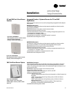
Mounting the Remote Human
Interface (RHI) Panel
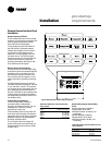
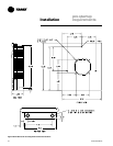
The installer must provide all mounting
hardware such as; hand tools, electrical
boxes, conduit, screws, etc. Refer to
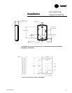
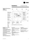
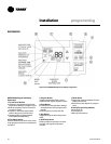
Figure I-PR-24 for the mounting hole and
knockout locations.
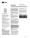
Procedure
Refer to Figure I-PR-24 and follow the
procedure below for mounting the
remote HI panel on a 4” by 4” electrical
junction box. Place the microprocessor in
a clean dry location during the enclosure
mounting procedures to prevent
damage.
1. Mount an electrical junction box in the
wall so that the front edge of the box
will be flush with the finished wall
surface.
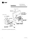
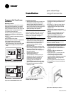
2. Prior to mounting the panel, the
microprocessor module must be
carefully removed from the enclosure.
To remove the module:
a. Lay the remote panel face up on a flat
surface and remove the locking screw
from the right hand bottom end of the
panel.
b. Remove the recessed hinge screw
from the left hand bottom end of the
panel.
c. Unlatch the door of the enclosure as if
to open it, and slide the left hand side of
the door upward away from the hinge.
Lay it aside.
d. With the key pad visible, remove the
two (2) screws located on the right hand
side of the key pad.
e. Carefully slide the key pad plate
upward from the bottom, releasing the
extruded hinge pin from its socket at
the top.
f. Set the microprocessor aside until
mounting is complete.
3. Remove the junction box knockout in
the back of the enclosure.
Note: The top of the enclosure is marked
“TOP.”
4. With the enclosure in the correct
position; align the mounting holes
around the knockout in the enclosure
with the screw holes in the electrical
handy box and secure with the
appropriate screws.
5. Replace the microprocessor within the
enclosure as follows:
a. Verify that the terminal block jumpers
are connected properly.
b. Slide the extruded hinge pin at the top
left of the key pad plate into the hole
located at the top left hand side of the
enclosure.
c. Slide the bottom of the plate into place,
aligning the two (2) clearance holes
with the screw holes on the right. Install
the screws but do not tighten.
Note: If the two screws are not installed as
called out in the previous step, hold against
the key pad plate while installing the door
in the next step, to prevent it from falling
out.
d. Slide the extruded hinge pin at the top
left of the door into the hole located
under the bottom left side of the display.
e. Install and tighten the hinge screw
located at the bottom left side of the
enclosure.
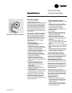
Wall Mounting the RHI Panel
1. Prior to mounting the panel, the
microprocessor module must be
removed from the enclosure. Complete
step 2 in the previous discussion,
“Mounting on a 4 in. x 4 in. Electrical
Box,” before proceeding.
2. With the microprocessor removed,
refer to Figure I-PR-24 for the location of
the mounting holes to be used for wall
mounting.
3. Place the enclosure against the
mounting surface and mark the
mounting holes.
Note: The top of the enclosure is marked
with “TOP.”
4. With the enclosure in the correct
position, remove the enclosure and drill
the necessary holes in the surface for
the appropriate fasteners, (plastic
anchors, molly bolts, screws, etc.)
5. Remove the necessary knockouts for
the wire or conduit entry before
mounting the panel.
6. Place the enclosure back onto the
surface and secure it with the
appropriate screws.
7. Follow step 5 in the previous section,
“Mounting on a 4” by 4” Electrical
Box,” to replace the microprocessor
within the enclosure.
Installation