


30 SCXG-SVX01B-EN
Water Piping
ƽƽ
ƽƽ
ƽ
WARNING
High Pressure Water!
Provide relief valves on system water
piping to prevent instantaneous release
of high pressure water. Failure to provide
relief valves could result in death or
serious injury or water pump damage or
unit failure.
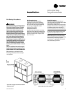
Condenser Connections
Condenser water piping knockouts are in
the lower left end panel. If necessary,
remove insulation to gain access. All field
installed piping must conform to
applicable local, state, and federal codes.
To complete condenser water
connections follow the procedure below.
Note: Four condenser waterline drain plugs
ship in a bag in the unit’s left end. The
installer must field install these four plugs
using pipe thread sealer. An additional plug
is provided for units with a waterside
economizer.
1. Attach the water supply line to the inlet
connection, and the return line to the
outlet connection. Entering and leaving
water connections for all condensers
are factory manifolded and require only
single connections for entering and
leaving water. If the unit has a
waterside economizer and/or control
valves, the factory pipes between these
components.
2. If using a cooling tower, refer to Figure
I-MR-2 for a typical piping circuit from
the unit.
3. Ensure the water pressure to the unit
does not exceed 400 psig.
Note: To prevent water pump damage,
design system piping to provide relief
when using energy saving waterside
economizer valves.
Duct Connections
ƽƽ
ƽƽ
ƽ
WARNING
Hazardous Voltage w/Capaci-
tors!
Disconnect all electric power, including
remote disconnects before servicing.
Follow proper lockout/tagout proce-
dures to ensure the power cannot be
inadvertently energized. For variable
frequency drives or other energy storing
components provided by Trane or others,
refer to the appropriate manufacturer’s
literature for allowable waiting periods
for discharge of capacitors. Verify with an
appropriate voltmeter that all capacitors
have discharged. Failure to disconnect
power and discharge capacitors before
servicing could result in death or serious
injury.
Note: For additional information regard-
ing the safe discharge of capacitors, see
PROD-SVB06A-EN or PROD-SVB06A-FR.
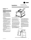
Return air enters the rear of the unit and
conditioned supply air discharges through
the top. Attach supply air ductwork
directly to the unit’s top panel, around the
fan discharge opening. A duct collar is not
provided.
Note: Units equipped with the flexible
horizontal discharge plenum option may
include a duct collar when holes are factory
cut. If discharge openings are field-cut, refer
to the “Plenum Installation” section.
Install all air ducts according to the
National Fire Protection Association
standards for the “Installation of Air
Conditioning and Ventilation Systems
other than Residence Type (NFPA 90A)
and Residence Type Warm Air Heating
and Air Conditioning Systems (NFPA
90B).
Make duct connections to the unit with a
flexible material such as heavy canvas. If
a fire hazard exists, Trane recommends
using Flexweave 1000, type FW30 or
equivalent canvas. Use three inches for
the return duct and three inches for the
discharge duct. Keep the material loose to
absorb fan vibration.
Note: The compressors and fan assembly are
internally isolated. Therefore, external isolation
devices (spring mounting isolators) are at the
discretion of a vibration specialist consulted
by the building or HVAC system designer.
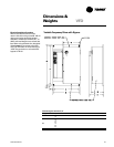
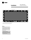
Run the ductwork straight from the
opening for a minimum of three fan
diameters. See Figure I-MR-1. Extend
remaining ductwork as far as possible
without changing size or direction. Do not
make abrupt turns or transitions near the
unit due to increased noise and excessive
static losses. Use elbows with splitters or
turning vanes to minimize static losses.
Poorly constructed turning vanes may
cause airflow generated noise. Align the
fan outlet properly with the ductwork to
decrease noise levels in the duct and to
increase fan performance. To complete
trunk ductwork to the VAV terminal units,
refer to the VAV box manuals for specific
requirements. Check total external static
pressures against fan characteristics to
be sure the required airflow is available
throughout the ductwork.
To achieve maximum acoustical perfor-
mance, minimize the duct static pressure
setpoint.
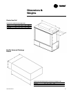
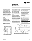
Figure I-MR-1. Duct connection recommenda-
tions
3 Fan
Diameters
Discharge
Duct
3-inch
Flexible
Duct
Return
Air
Mechanical
Specifications