


SCXG-SVX01B-EN 105
System Checks
ƽƽ
ƽƽ
ƽ
WARNING
Live Electrical Components!
During installation, testing, servicing and
troubleshooting of this product, it may be
necessary to work with live electrical
components. Have a qualified licensed
electrician or other individual who has
been properly trained in handling live
electrical components perform these
tasks. Failure to follow all electrical
safety precautions when exposed to live
electrical components could result in
death or serious injury.
Before proceeding with technical trouble
charts or controls checkout, complete the
following system analysis:
1. Measure actual supply voltage at the
compressor and an motor terminals
with the unit running. Voltage must be
within the range listed on the motor
nameplate. Phase imbalance must be
less than 2.0%.
2. Check all wiring and connections to be
sure that they are intact, secure and
properly routed. The as wired system
diagrams are provided in the unit
control panel.
3. Check that all fuses are installed and
properly sized.
4. Inspect air filters and coils to bel sure
that airflow to the unit is not restricted.
5. Check the zone thermostat settings.
6. Ensure that the fan is rotating in the
proper direction. If phasing is wrong at
the main power terminal block, the fan
and compressors will not run correctly.
7. Inspect ductwork and duct connections
for tightness.
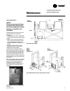
Operating Procedures
Install pressure gauges on the discharge
and suction line access valves. When the
unit has stabilized (after operating
approximately 15 minutes at full load),
record suction and discharge pressures.
System malfunctions such as low airflow,
line restrictions, incorrect refrigerant
charge, malfunctioning of expansion
valves, damaged compressors, etc. will
result in pressure variations which are
outside the normal range.
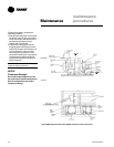
Note: If phasing at the main incoming
power terminal is incorrect, switch two of
the three incoming power leads. If a
compressor has been replaced and the
phase is changed at the compressor, it will
run backwards and discharge pressure will
be very low. To resolve incorrect compres-
sor wire phasing, change phasing at the
compressor.
It is important that pressures be mea-
sured under stable and constant condi-
tions in order for the readings to be
useful.
Voltage Imbalance
Voltage imbalance on three-phase
systems can cause motor overheating
and premature failure. Maximum
allowable imbalance is 2.0%, and the
readings used to determine it must be
measured at the compressor terminals.
Voltage imbalance is defined as 100
times the sum of the division of the three
voltages from the average voltage. If, for
example, the three measured voltages
are 221, 230, 227, the average is:
(221+230+227) = 226 volts
3
Therefore, the percentage of voltage
imbalance is:
100*(226-221) = 2.2%
226
In this example, 2.2% imbalance of more
than 2.0% exists, be sure to check the
voltage at the unit disconnect and
terminal block switch. If an imbalance at
the unit disconnect switch does not
exceed 2.0%, the imbalance is caused by
faulty wiring within the unit. Be sure to
conduct a thorough inspection of the unit
electrical wiring connections to locate the
fault, and make any repairs necessary.
troubleshootingMaintenance
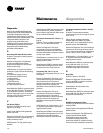
Common Unit Problems and Solutions
Problem Possible Cause Remedy
Drain pan is overflowing Plugged drain line Clean drain line
Unit not level Level unit
Standing water in drain pan Unit not level Level Unit
Plugged drain line Clean drain line
Wet interior insulation Coil face velocity too high Reduce fan speed
Improper trap design Design trap per unit installation instructions
Drain pan leaks/overflowing Repair Leaks
Condensation on surfaces Insulate surfaces
Excess dirt in unit Missing filters Replace filters
Filter bypass Reduce filter bypass
Microbial growth (mold) Standing water in drain pan See “Standing water in drain pan” above
Moisture problems See “Wet interior insulation” above