


SCXG-SVX01B-EN 89
Low Ambient Compressor Lockout
This function will lock out the compressor
if the outdoor air temperature sensor
reads an outdoor temperature below the
low ambient compressor lockout
temperature setpoint. This setpoint is
adjustable at the human interface panel.
Compressors will lock out when outdoor
air temperature falls below that selected
temperature and will start again when
the temperature rises 5°F above the
setpoint.
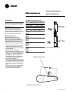
Evaporator Coil Frost Protection
FROSTAT
™
The FROSTAT
™
system eliminates the
need for hot gas bypass. It utilizes an
evaporator temperature sensor mounted
on the suction line near the TXV bulb of
each circuit to protect the evaporator
from freezing.
If the evaporator temperature ap-
proaches the specified setpoint (adjust-
able between 25 and 35°F at the HI) the
compressor(s) will cycle off. The supply
fan remains on to help de-ice the coil. The
compressors will restart when the
evaporator temperature has risen 10°F
above the specified cutout temperature
and when the compressor(s) have been
off a minimum of three minutes. This
prevents rapid cycling of the compres-
sors.
sequence of
operation
Compressor Safety Devices
The compressors have motor
temperature cutout switches in the motor
windings. These switches are provided
to take the compressors off line during
high motor winding temperature
conditions.
If a compressor low pressure cutout
opens during compressor start-up, the
UCM will not shut the compressor off
during the first two to three minutes after
start-up. This prevents possible nuisance
trips during low ambient start conditions.
See Table O-SO-2.
Each compressor’s discharge line
contains a high pressure cutout. Under
abnormal operating conditions, the cutout
will open to stop compressor operation.
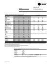
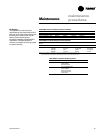
Table O-SO-2. Pressure cutouts
Unit High Pressure Low Pressure
Model Cutout Cutout
SXWF 360/270 20/35
SXRF 405/350 12/27
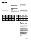
Step Control
Steps of mechanical cooling are control
based on supply air or zone temperature.
See Table O-SO-1 for compressor
staging.
Capacity is based on an integrating
control concept. The unit capacity
matches the existing load and maintains
an average supply air temperature within
the supply air setpoint temperature
control band region.
The supply air temperature control band
is centered around supply air tempera-
ture setpoint and is adjustable from 2 to
12°F. In a steady state, the unit will either
maintain a constant level of cooling
capacity with the supply air temperature
within the control band, or the highest
active cooling level will cycle to provide
an average supply air temperature equal
to the setpoint.
If the supply air temperature swings
outside the limits of the control band, the
mechanical cooling capacity will increase
or decrease by one level accordingly. The
change occurs by integrating the tem-
perature offset from the control band
limit.
A minimum time delay of five minutes
follows each change in cooling level. This
time delay promotes stability by allowing
the system to respond to the change
before any further control action occurs.
As the supply air temperature ap-
proaches setpoint, the time duration
between changing levels of cooling
capacity increases.
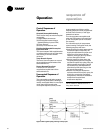
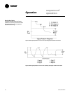
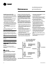
See Figure O-SO-2 for the typical unit
operating curve. Figure O-SO-3 shows
typical unit performance when supply air
temperature swings exceed the control
band limits.
Adjust the supply air temperature control
band according to the desired unit
performance. Increasing the control band
reduces the equipment cycle rate and
increases the maximum potential supply
air temperature deviation from setpoint.
Conversely, decreasing the control band
reduces the maximum potential tem-
perature deviation, but increases the
compressor cycle rate.
Follow these recommendations concern-
ing the supply air temperature control
band settings based on expected unit
sizing:
2 Cooling stage unit: 9°F
3 Cooling stage unit: 7°F
4 Cooling stage unit: 6°F
Operation