


SCXG-SVX01B-EN 33
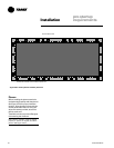
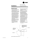
Specific unit wiring diagrams are
provided on the inside of the control
panel door. Use these diagrams for
connections or trouble analysis.
Supply Power Wiring
ƽƽ
ƽƽ
ƽWARNING
Hazardous Voltage w/Capacitors!
Disconnect all electric power, including
remote disconnects before servicing.
Follow proper lockout/tagout proce-
dures to ensure the power cannot be
inadvertently energized. For variable
frequency drives or other energy storing
components provided by Trane or others,
refer to the appropriate manufacturer’s
literature for allowable waiting periods
for discharge of capacitors. Verify with an
appropriate voltmeter that all capacitors
have discharged. Failure to disconnect
power and discharge capacitors before
servicing could result in death or serious
injury.
Note: For additional information regard-
ing the safe discharge of capacitors, see
PROD-SVB06A-EN or PROD-SVB06A-FR.
It is the installer’s responsibility to
provide power supply wiring to the unit
terminal block or the non-fused
disconnect switch option. Wiring should
conform to NEC and all applicable code
requirements.
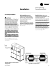
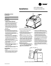
Bring supply wiring through the knockout
in the lower left side of the unit control
panel. Connect the three phase wires to
the power terminal block or the non-
fused disconnect switch in the control box
terminals. Refer to specific wiring
diagrams and fuse information in the
unit’s control panel.
NOTICE
Use Copper Conductors Only!
Unit terminals are not designed to
accept other type conductors. Failure to
use copper conductors may result in
equipment damage.
NOTICE
Equipment Damage!
Correct phase sequence is critical. If
phase sequence of the incoming line
voltage is not correct, it may result in
motor damage.
Voltage Range
Voltages must be within +- 10% the
nameplate voltage. Ensure the unit
voltage is balanced by measuring at the
compressor terminals. Voltage imbalance
on three phase systems can cause motor
overheating and premature failure.
Maximum allowable imbalance is 2.0%.
Voltage Imbalance
Read the voltage at the compressor
terminals to determine if it is balanced.
Voltage imbalance on three phase
systems can cause motor overheating
and premature failure. The maximum
allowable imbalance is 2.0%. Voltage
imbalance is defined as 100 times the
sum of the deviation of the three voltages
from the average (without regard to sign)
divided by the average voltage. For
example, if the three measured voltages
are 221, 230, and 227, the average voltage
would be:
(221 + 230 + 227) = 226 volts
3
The percentage of voltage imbalance is
then:
100 *
(226-221) = 2.2%
226
Electrical
Requirements
ƽƽ
ƽƽ
ƽWARNING
Live Electrical Components!
During installation, testing, servicing and
troubleshooting of this product, it may be
necessary to work with live electrical
components. Have a qualified licensed
electrician or other individual who has
been properly trained in handling live
electrical components perform these
tasks. Failure to follow all electrical
safety precautions when exposed to live
electrical components could result in
death or serious injury.
Control Power
NOTICE
Component Failures!
Unit transformers IT1, IT3, 1T4, and IT5
are sized to provide power to the unit
only. Do not use these transformers to
supply power to field equipment. Field
connections to these transformers may
create immediate or premature compo-
nent failures.
In this example, 2.2% imbalance is not
acceptable. Whenever a voltage
imbalance of more than 2.0% exists,
check the voltage at the unit disconnect
switch. If the imbalance at the unit
disconnect switch does not exceed 2.0%,
faulty unit wiring is causing the
imbalance. Conduct a thorough
inspection of the unit electrical wiring
connections to locate the fault, and make
any repairs necessary.
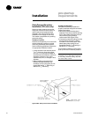
Access the connection terminal block
through the control panel on the unit’s
upper left side. All wiring should conform
to NEC and applicable local code require-
ments.
Be sure all wiring connections are secure.
Reference the unit specific diagrams
inside the control panel.
Unit Wiring Diagrams