


92
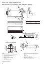
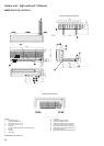
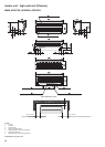
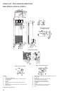
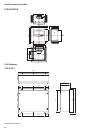
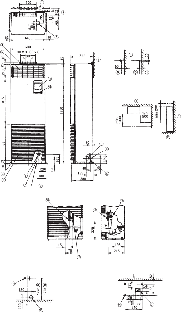
Indoor unit - floor-mounted cabinet unit
MMF-AP0361H, AP0481H, AP0561H
All dimensions are given in mm.
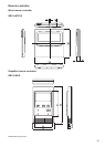
Legend
1. Wall
2. With 50 mm wall clearance
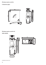
3. Lower refrigerant pipe connection (50 x 120 knockout hole)
4. Installation plate
5. Air outlet
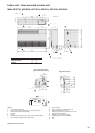
6. Air inlet
7. Refrigerant pipe connection (rear) (Ø130 knockout hole)
8. Drain hose
9. Refrigerant pipe connection (bottom) (50 x 120 knockout hole)
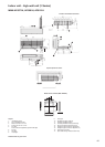
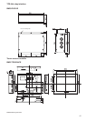
10. Earth screw M4
11. Refrigerant pipe connection (both sides) (Ø80 knockout hole)
12. Control panel
13. Panel cover
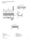
14. 2-lower hole (for M8 screw or M8 anchor bolt)
15. Ø130 knockout hole (for rear piping)
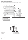
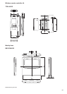
16. Refrigerant pipe connection (gas Ø3/4”)
17. Refrigerant pipe connection (liquid Ø3/8”)
18. Liquid side
19. Gas side
20. 4-lower hole (for M8 screw or M8 anchor bolt)
21. 50 x 120 square hole (for bottom piping)
22. Floor
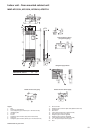
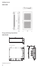
Space required for service
(for right-hand piping)
Front
Front
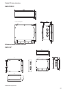
Refrigerant pipe positions
Details of hole for bottom piping
Details of hole for rear piping