


86
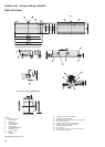
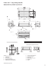
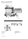
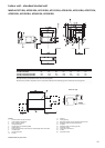
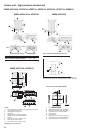
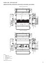
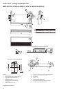
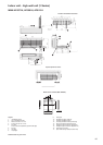
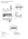
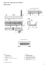
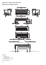
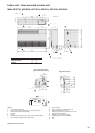
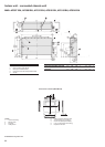
Indoor unit - high-wall unit (1 Series)
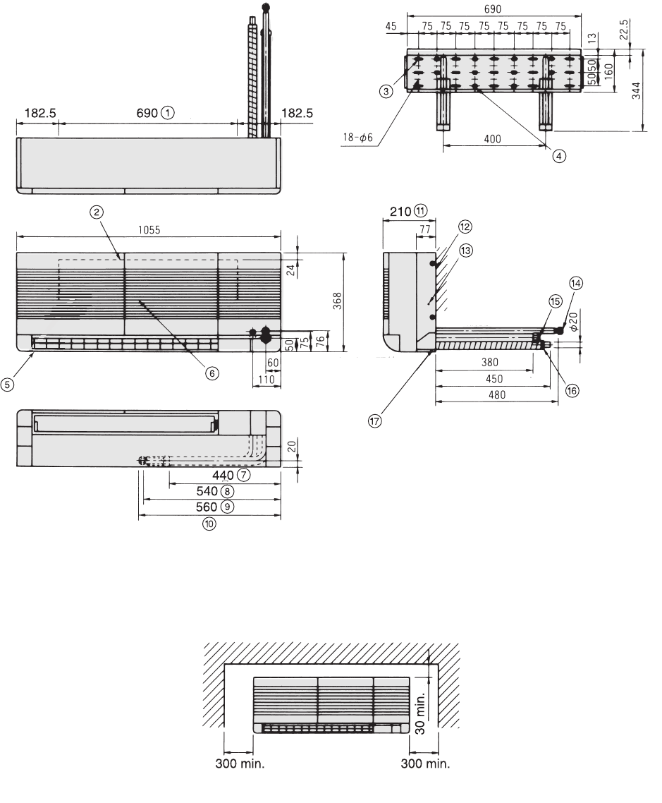
MMK-AP0151H, AP0181H
All dimensions are given in mm.
Legend
1. (Installation board)
2. Top of installation board
3. Wood screw slot 15-6 x 30
4. Anchor bolt slot 10-10 x 20
5. Air outlet
Air flow direction adjustable (up/down/left/right)
6. Air inlet
7. Gas pipe
8. Liquid pipe
9. Drain pipe
10. Supplied with pipe outlet left
11. Including installation board
12. Including installation board (accessory)
13. Earth screw (M4) (inside control box)
14. Refrigerant pipe connection (gas Ø1/2”)
15. Refrigerant pipe connection (liquid Ø1/4”)
16. Drain pipe connection
17. Pipe outlet left/right side (knockout hole)
Position of installation board hole
Space required for service