


26
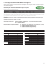
Procedure and result of equipment selection
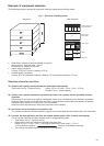
1. Procedure of equipment selection
a. Calculate cooling for every room.
b. Select an indoor unit to match the cooling load for every room from the table on page 10.
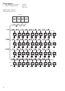
c. Select the outdoor module to match the indoor units selected in point b. Select the outdoor modules
based on the critical factors and the combination rule. Choose a tentative outdoor module that will match
the indoor units, and check whether the selection agrees with the combination rule. Perform the capacity
correction based on the pipe length, system lift, indoor set temperature, outdoor temperature.
Then, make sure the corrected system cooling capacity satisfies the cooling load.
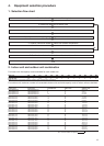
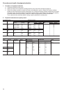
2. Equipment selection and capacity check
Air conditioning load Equipment selection
Floor Room No. Indoor air conditioning
load (kW) Indoor unit Outdoor unit
Model Capacity (kW) Model Capacity (kW)
Cooling Heating MMU- Cooling Heating
MMY Cooling Heating
4F 4-1 6.0 (16 o’clock) 5.4 AP0241H 7.1 8.0 AP2801HT8 78.5 88.0
4-2 5.2 (14 o’clock) 4.2 AP0181H 5.6 6.3
4-3 5.0 (14 o’clock) 4.2 AP0181H 5.6 6.3
4-4 3.2 (12 o’clock) 2.7 AP0121H 3.6 4.0
4-5 6.4 (10 o’clock) 5.4 AP0241H 7.1 8.0
3F 3-1 12.7 12.0 AP0481H 14.0 16.0
2F 2-1 4.8 4.5 AP0181H 5.6 6.3
2-2 4.6 4.8 AP0181H 5.6 6.3
2-3 — — — — —
1F 1-1 6.5 6.0 AP0241H 7.1 8.0
1-2 6.5 6.3 AP0241H 7.1 8.0
1-3 7.2 7.0 AP0301H 9.0 10.0
1-4 5.1 4.5 AP0181H 5.6 6.3
Note: ( ): Peak occurrence time
Piping distance Capacity correction Capacity check after correction
Floor Room No. Equivalent
Height Pipe correction x Capacity (kW) Result
length (m) difference (m) temp. correction
Cooling Heating Cooling Heating
4F 4-1 43 12 0.920 0.957 6.5 6.9 Good
4-2 x x 5.2 5.4
4-3 1.0 1.0 5.2 5.4
4-4 x x 3.3 3.5
4-5 1.0 0.95 6.5 6.9
3F 3-1 = x 12.9 13.8
2F 2-1 0.920 0.95 5.2 5.4
2-2 = 5.2 5.4
2-3 0.864 — —
1F 1-1 6.5 6.9
1-2 6.5 6.9
1-3 8.3 8.6
1-4 5.2 5.4