


32
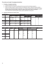
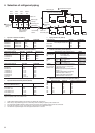
4. Selection of refrigerant piping
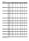
Pipe size of outdoor unit (Table 1)
Model name MMY- Gas side Liquid side
MAP0501T8 MAP0501HT8 Ø5/8” Ø3/8”
MAP0601T8 MAP0601HT8 Ø3/4” Ø3/8”
MAP0801T8 MAP0801HT8 Ø7/8” Ø1/2”
MAP1001T8 MAP1001HT8 Ø7/8” Ø1/2”
MAP1201T8 MAP1201HT8 Ø1-1/8” Ø1/2”
Connecting pipe size between outdoor units (Table 2)
Total capacity code of Gas side Liquid side Balance pipe
outdoor units downstream
14 to below 22 Ø1-1/8” Ø5/8” Ø3/8”
22 to below 26 Ø1-3/8” Ø5/8” Ø3/8”
26 to below 36 Ø1-3/8” Ø3/4” Ø3/8”
36 or more Ø1-5/8” Ø7/8” Ø3/8”
Size of main pipe (Table 3)
Total capacity code of Gas side Liquid side
all outdoor units (*1)
Below 6 Ø5/8” Ø3/8”
6 to below 8 Ø3/4” Ø3/8”
8 to below 12 Ø7/8” Ø1/2”
12 to below 14 Ø1-1/8” Ø1/2”
14 to below 22 Ø1-1/8” Ø5/8”
22 to below 26 Ø1-3/8” Ø5/8”
26 to below 36 Ø1-3/8” Ø3/4”
36 to below 46 Ø1-5/8” Ø7/8”
46 or more Ø1-5/8” (*5) Ø7/8”
Determine thickness of the main pipe according to capacity of the outdoor units.
Pipe size between branching sections (Table 4)
Total capacity code of Gas side Liquid side
indoor units downstream (*1)
2.8 or less Ø1/2” Ø3/8”
2.8 to below 6.4 Ø5/8” Ø3/8”
6.4 to below 12.2 Ø7/8” Ø1/2”
12.2 to below 20.2 Ø1-1/8” Ø5/8”
20.2 to below 25.2 Ø1-3/8” Ø5/8”
25.2 to below 35.2 Ø1-3/8” Ø3/4”
35.2 or more Ø1-5/8” Ø7/8”
If the total capacity code value of indoor units exceeds that of the outdoor units,
apply the capacity code of the outdoor units.
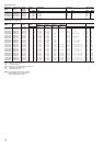
Piping of indoor unit (Table 5)
Indoor unit size Gas side Liquid side
007 to 012 Actual length 15 m or less Ø3/8” Ø1/4”
Actual length exceeds 15 m Ø1/2” Ø1/4”
015 to 018 Ø1/2” Ø1/4”
024 to 056 Ø5/8” Ø3/8”
072 to 096 Ø7/8” Ø1/2”
Selection of branching section (Table 6)
Total capacity code of indoor unit (*1) Model
Y-shape Below 6.4 RBM-BY53E
branching joint 6.4 to below 14.2 RBM-BY103E
(*2) 14.2 to below 25.2 RBM-BY203E
25.2 or more RBM-BY303E
Branching For 4 Below 14.2 RBM-HY1043E
header branching 14.2 to below 25.2 RBM-HY2043E
(*3) For 8 Below 14.2 RBM-HY1083E
branching 14.2 to below 25.2 RBM-HY2083E
T-shape 1 set of 3 types of T-shape joint pipes as RBM-BT13E
branching joint described below:
(For connecting The required quantity is arranged and
outdoor unit) combined at the site.
• Balance pipe (Corresponding difference
Ø3/8”) × 1
• Piping at liquid side (Corresponding
difference Ø3/8” to Ø7/8”) × 1
• Piping at gas side (Corresponding
difference Ø5/8” to Ø1-5/8”) × 1
Minimum wall thickness for R-410A application (Table 7)
Soft Half hard or hard OD (Inch) Minimum wall thickness (mm)
OK OK 1/4” 0.80
OK OK 3/8” 0.80
OK OK 1/2” 0.80
OK OK 5/8” 1.00
NG OK (*4) 3/4” 1.00
NG OK (*4) 7/8” 1.00
NG OK (*4) 1-1/8” 1.00
NG OK (*4) 1-3/8” 1.10
NG OK (*4) 1-5/8” 1.25
*1 Code is determined according to the unit size. For details, refer to pages 7-9.
*2 When using Y-shape branching joint for 1st branching, select according to capacity code of outdoor unit.
*3 For one line after header branching, indoor units with a maximum of 6.0 capacity code in total can be connected.
*4 If the pipe size is Ø3/4” or more, use a hard type or half hard type for material of the pipe.
*5 The maximum equivalent length of the main pipe should be 70 m or shorter.
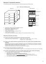
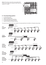
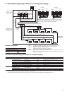
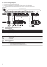
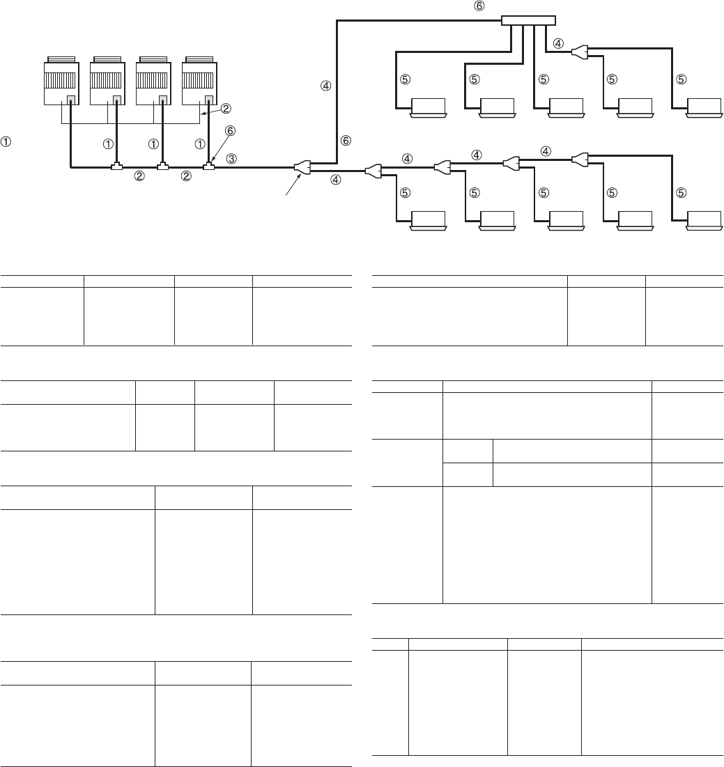
Slave
unit 3
Slave
unit 2
Slave
unit 1
Master
unit
Outdoor unit
Balance pipe
T-shape
branching joint
Main piping
Outdoor unit
connection
piping
Main connection
piping between
outdoor units
1st branching
section
Indoor unit
connection piping
Indoor unit
Y-shape
branching
joint
Indoor unit connection piping
Header branching pipe
Indoor unit
Branching pipe