


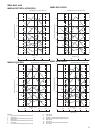
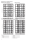
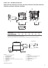
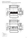
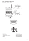
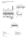
81
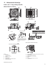
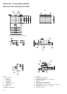
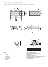
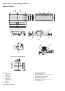
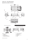
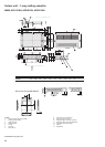
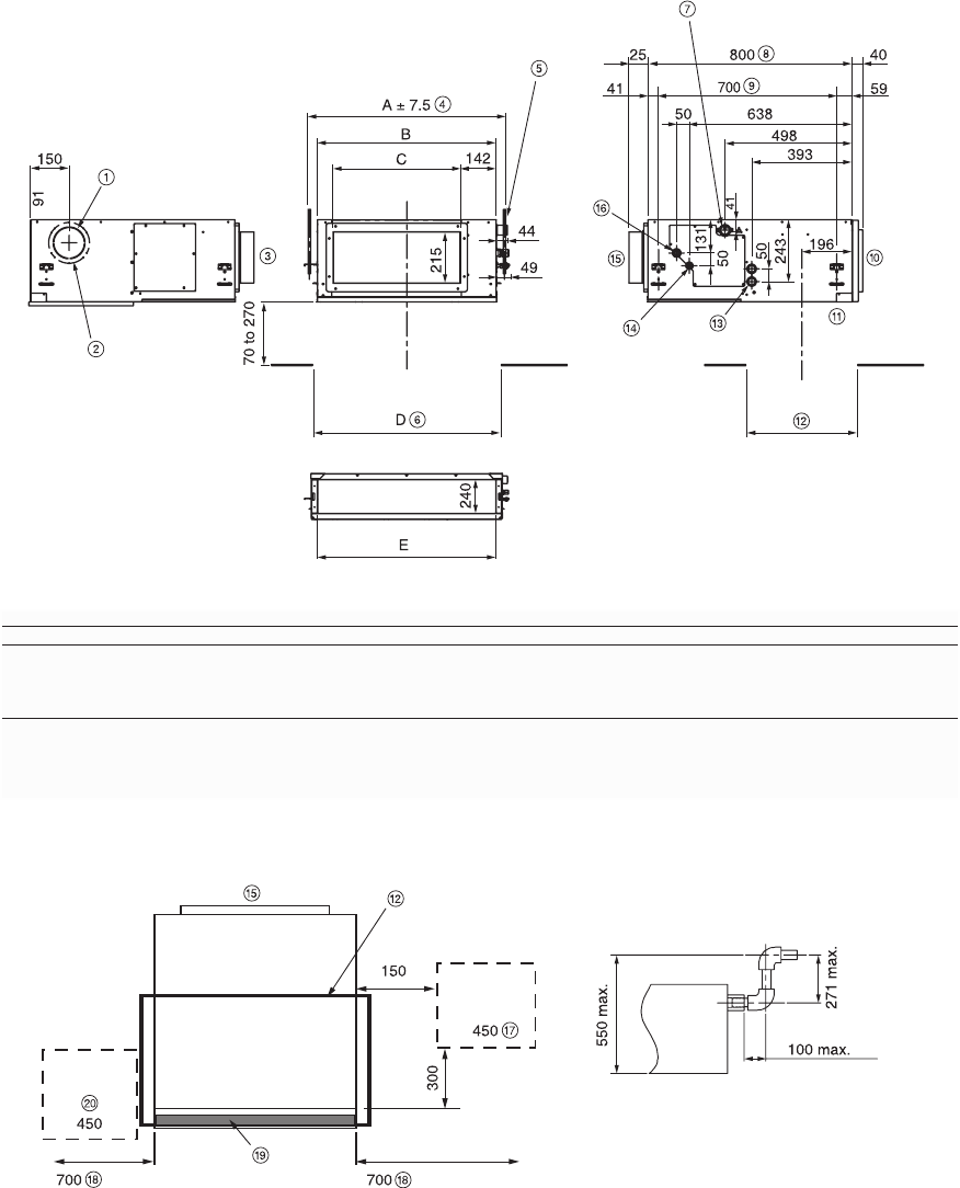
Indoor unit - standard ducted unit
MMD-AP0071BH, AP0091BH, AP0121BH, AP0151BH, AP0181BH, AP0241BH, AP0271BH,
AP0301BH, AP0361BH, AP0481BH, AP0561BH
All dimensions are given in mm.
Legend
1. Ø125 knockout hole (for air intake)
2. 10-Ø4 tapping screw Ø160
3. When attaching directly
4. Hanging bolt pitch
5. Hanging bolt 4-M10 (field-supplied)
6. Ceiling opening
7. Drain pipe connection (inner Ø32 vinyl chloride pipe VP25 connection)
8. Unit dimension
9. Hanging bolt pitch
10. Air inlet
11. Panel CL
12. Ceiling opening
13. Ø26 power supply, remote controller cable conduit
14. Refrigerant pipe connection (liquid ØG)
15. Air outlet
16. Refrigerant pipe connection (gas ØF)
17. Inspection hole A
18. For air filter maintenance
19. Air filter
20. Inspection hole B
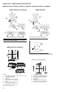
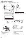
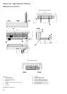
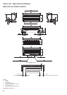
Drain riser pipe
Model MMD- A B C D E ØF ØG
AP0071BH, AP0091BH, AP0121BH 616 550 350 600 470 3/8” 1/4”
AP0151BH, AP0181BH 766 700 500 750 620 1/2” 3/8”
AP0241BH, AP0271BH, AP0301BH 1066 1000 800 1050 920 5/8” 3/8”
AP0361BH, AP0481BH, AP0561BH 1416 1350 1150 1400 1270 5/8” 3/8”
Note: High-efficiency and deodorant filters cannot be used together.
Note: Be sure to provide an inspection hole A in the position indicated in the following figure for maintenance of the equipment.