33
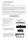
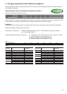
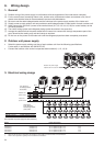
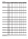
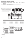
5. Charging requirement with additional refrigerant
After the system has been evacuated, replace the vacuum pump with a refrigerant cylinder and charge the system
with additional refrigerant.
Calculating the amount of additional refrigerant required
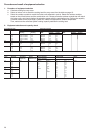
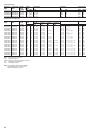
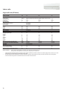
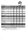
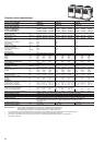
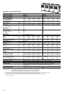
Refrigerant in the system when shipped from the factory
5 hp 6 hp 8 hp 10 hp 12 hp
Factory refrigerant Heat pump 8.5 kg 8.5 kg 12.5 kg 12.5 kg 12.5 kg
charge Cooling only 8.0 kg 8.0 kg 11.0 kg 11.0 kg 11.0 kg
When the system is charged with refrigerant at the factory, the amount of refrigerant needed for the pipes at the site
is not included. Calculate the additional amount needed, and add that amount to the system.
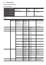
Calculation
Additional refrigerant charge amount is calculated from the size of the liquid pipe at the site and its actual length.
Additional refrigerant charge amount at the site =
Actual length of liquid pipe × Additional refrigerant charge amount + Compensation by system hp (Table 2)
per 1 m liquid pipe (Table 1)
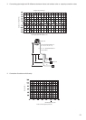
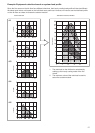
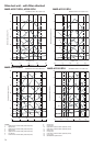
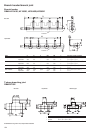
Example: Additional charge amount R (kg) = (L1 x 0.025 kg/m) + (L2 x 0.055 kg/m) + (L3 x 0.105 kg/m) + (3.0 kg)
L1: Actual total length of liquid pipe Ø1/4” (m)
L2: Actual total length of liquid pipe Ø3/8” (m)
L3: Actual total length of liquid pipe Ø1/2” (m)
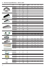
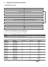
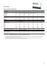
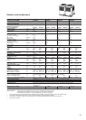
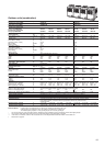
Table 7-1
Liquid side pipe diameter Ø1/4” Ø3/8” Ø1/2” Ø5/8” Ø3/4” Ø7/8”
Additional refrigerant amount/1 m 0.025 kg 0.055 kg 0.105 kg 0.160 kg 0.250 kg 0.350 kg
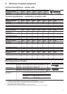
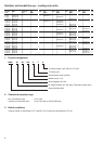
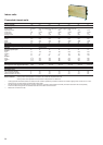
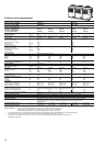
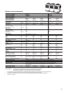
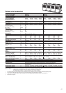
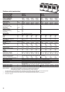
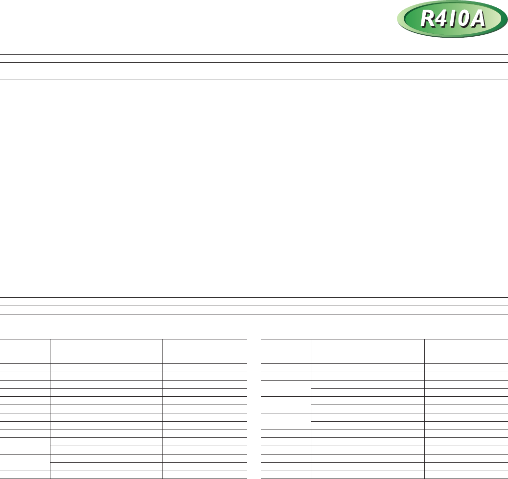
Table 7-2
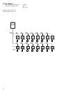
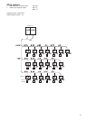
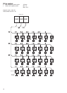
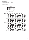
Combined Outdoor unit combination Compensation
horse power (hp) by system hp
(hp) (kg)
28 10 10 8 -2.0
30 10 10 10 0.0
32 12 10 10 1.0
8 8 8 8 -6.0
34 12 12 10 3.0
10 8 8 8 -6.0
36 12 12 12 4.0
10 10 8 8 -6.0
38 10 10 10 8 -6.0
40 10 10 10 10
-5.0
42 12 10 10 10 -4.0
44 12 12 10 10 -2.0
46 12 12 12 10 0.0
48 12 12 12 12 2.0
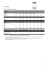
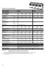
Combined Outdoor unit combination Compensation
horse power (hp) by system hp
(hp) (kg)
5 5 0.0
6 6 0.0
8 8 1.5
10 10 2.5
12 12 3.5
14 8 6 0.0
16 8 8 0.0
18 10 8 0.0
20 10 10 3.0
22 12 10 5.0
8 8 6 0.0
24 12 12 7.0
8 8 8 -4.0
26 10 8 8 -4.0