


89
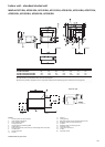
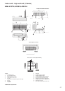
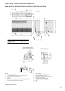
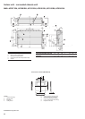
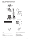
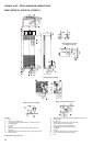
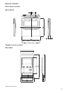
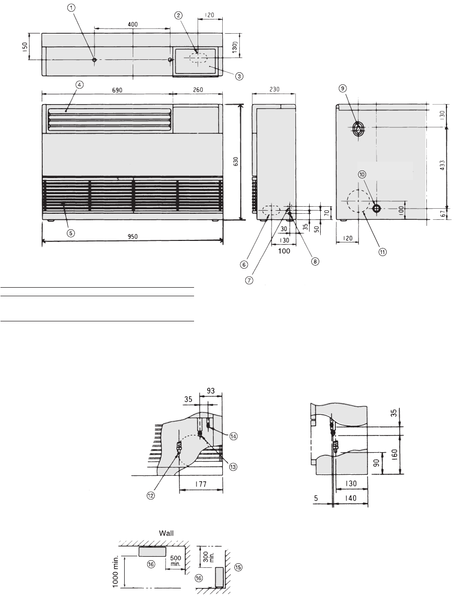
Indoor unit - floor-mounted console unit
MML-AP0071H, AP0091H, AP0121H, AP0151H, AP0181H, AP0241H
All dimensions are given in mm.
Legend
1. Hole for floor fixing (2-Ø10)
2. Lower refrigerant pipe connection (50 x 100 knockout hole)
3. Switch section (switch sold separately)
4. Air outlet
5. Air inlet
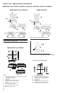
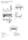
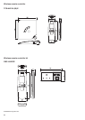
6. Refrigerant pipe connection (50 x 100 knockout hole) (both sides)
7. Power supply cord (Ø26 knockout) (both sides)
8. Earth screw M6
9. Hole for wall fixing (Ø10-Ø20 knockout x 2)
10. Hole for wall fixing (2-10 x 24 slot)
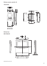
11. Refrigerant pipe connection (Ø130 knockout hole)
12. Drain pipe connection (Ø20)
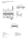
13. Refrigerant pipe connection (gas ØA)
14. Refrigerant pipe connection (liquid ØB)
15. Wall
16. Front
(left side)
Model MML- ØA ØB
AP0071H, AP0091H, AP0121H 3/8” 1/4”
AP0151H, AP0181H 1/2” 1/4”
AP0241H 5/8” 3/8”
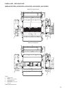
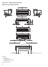
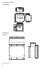
Space required for service
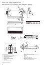
Figure shows left-hand piping
Pipe position diagram