


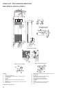
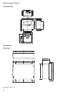
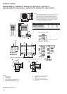
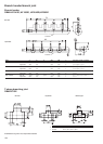

100
Outdoor module
MMY-MAP0501T8, MAP0601T8, MAP0801T8, MAP1001T8, MAP1201T8,
MMY-MAP0501HT8, MAP0601HT8, MAP0801HT8, MAP1001HT8, MAP1201HT8,
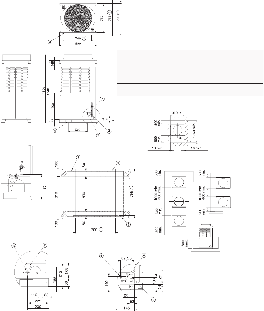
Legend
1. Anchor bolt pitch
2. (including feet)
3. 4-15 x 20 (slot)
4. 2-60 x 150 square hole (for forklift truck)
5. Balance pipe connection Ø3/8”
6. Refrigerant pipe connection (liquid ØB)
7. Refrigerant pipe connection (gas ØA)
8. Earthing section of bottom plate
9. Base
10. Knockout for control wiring (Ø27)
11. Knockout hole for power wiring (Ø48)
12. Square hole
All dimensions are given in mm.
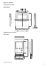
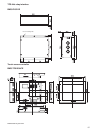
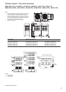
Notes:
1. If there is an obstacle at the top of the outdoor unit, ensure that
the top of the outdoor unit clears the obstacle by 2000 mm.
2. Ensure that the height of obstacles around the outdoor unit
does not exced 800 mm from the bottom of the outdoor unit.
3. Draw out the field-supplied pipe to the front of the outdoor unit
horizontally, and keep 500 mm or more between the outdoor
unit and pipe if placing the pipe transversely.
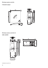
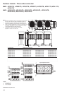
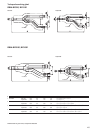
Model A B C
MMY-MAP0501T8, MAP0501H
T8 5/8” 3/8” 280
MMY-MAP0601T8, MAP0601HT8 3/4” 3/8” 280
MMY-MAP0801T8, MAP0801HT8 7/8” 1/2” (205)
MMY-MAP1001T8, MAP1001HT8 7/8” 1/2” (205)
MMY-MAP1201T8, MAP1201HT8 1-1/8” 1/2” (205)
*1 Cutting position of L-shape pipe when pipe is connected at the gas side.
(Recommended pipe connection position)
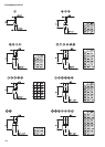
Front (for work and service)
Space required for service
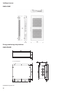
Details of front pipe/cabling holes
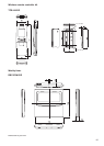
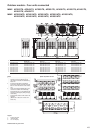
Details of hole for bottom piping (plane view)
Front
Front
Front
Note 3
Note 3
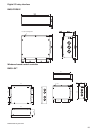
MMY-MAP0501T8
MMY-MAP0601T8
MMY-MAP0501HT8
MMY-MAP0601HT
8