


36
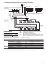
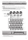
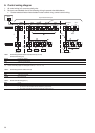
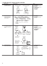
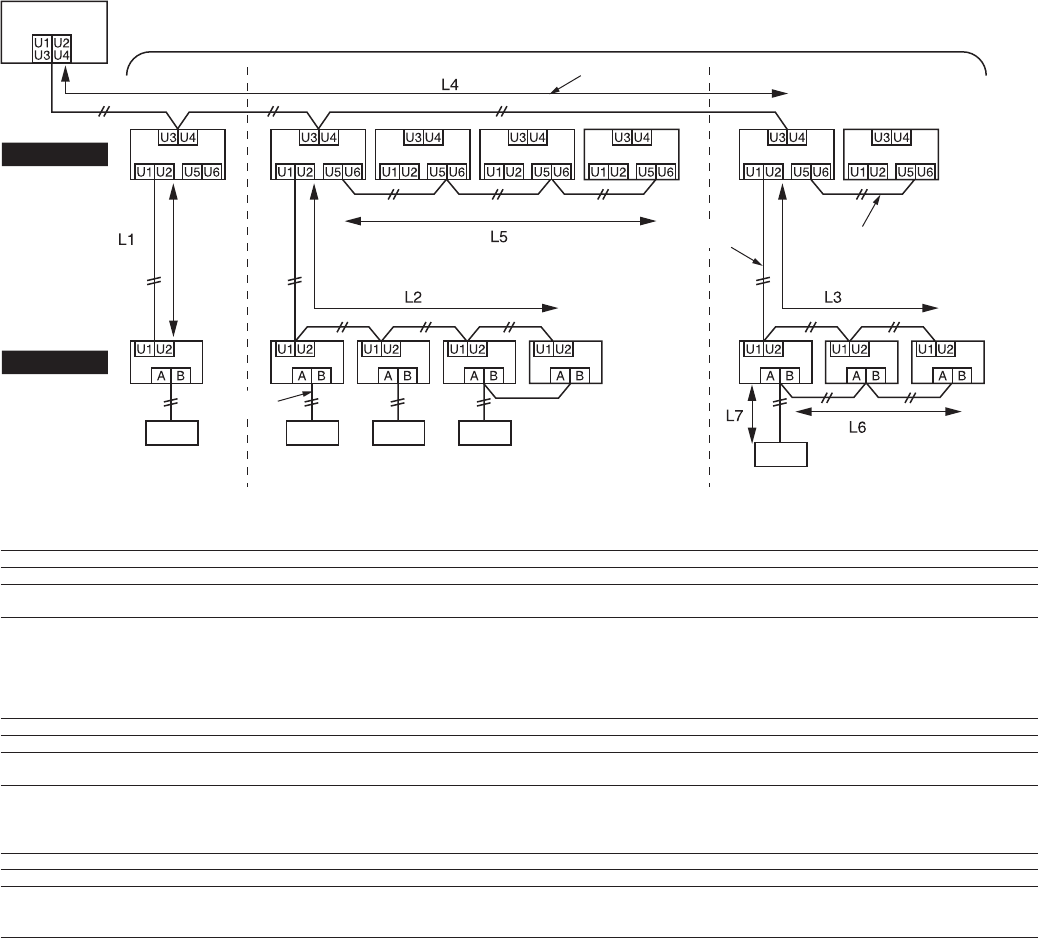
6. Control wiring diagram
1. All control wiring is 2-core non-polarity wire.
2. Be sure to use shielded wire for the following wiring to prevent noise disturbance.
• Outdoor-outdoor/indoor-indoor/outdoor-indoor control wiring, central control wiring.
Table 1 Control wiring between indoor and outdoor units (L1, L2, L3)
Central control wiring (L4)
Wiring 2-core, non-polarity
Type Shielded wire
Size 1.25 mm²: Up to 1000 m
Length 2.0 mm²: Up to 2000 m (*1)
(*1): Total of control wiring length for all refrigerant circuits ( L1 + L2 + L3 + L4 )
Table 2 Control wiring between outdoor units (L5)
Wiring 2-core, non-polarity
Type Shielded wire
Size 1.25 mm² to 2.0 mm²
Length Up to 100 m (L5)
Table 3 Remote controller wiring (L6, L7)
Wire 2-core
Size 0.5 mm² to 2.0 mm²
Length • Up to 500 m ( L6 + L7 ).
• Up 400 m in case of wireless remote controller in group control.
• Up to 200 m total length of control wiring between indoor units ( L6 ).
Central control
device
Super Modular Multi System
Table 1
Outdoor unit
Indoor unit
Master
unit
Master
unit
Master
unit
Slave
unit
Slave
unit
Slave
unit
Slave
unit
Table 1 Table 2
Table 3
Remote
controller
Remote controller
Remote controller