


36
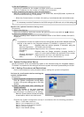
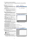
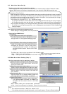
8.7.4 Creation of a plane view (Step 3)
Follow these steps to create a floor plane for each floor. This floor plane is used in air conditioning
operation and supervision for each floor. If not displaying a floor plane, it is not necessary to create
one.
Create a floor plane for each floor
[Procedure]
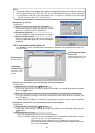
1) Click the Base [Change] button.
In the Floor Plan Settings window, click the
[Change] button to edit the flow chart. The paint
brush appears.
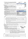
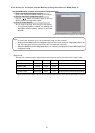
2) Create a floor plane flow chart.
Create a floor plane flow chart with the paint brush.
* For details, see the Windows 2000/XP users
guide.
3) Exit Paint Brush Mode.
Click the file menu and select the Exit Paint Brush
option. Select “Yes” on “the save confir- mation
screen”.
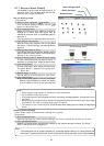
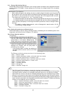
4) Select a floor using the “
/
” button
Use the “
/
” button to select the floor to be
modified.
5) Click the Base [Copy] button.
To apply the created flow chart to the selected
floor, click the Base [Copy] button. It is not
necessary to click the Base Copy button when
creating a new floor plane.
6) Click the [Change] button
To create or edit a floor plane for the selected floor,
click the [Change] button. The paint brush starts
up, and the floor plane can be edited.
7) Create a floor plane.
Use the paint brush to edit the floor plane of the selected floor.
8) Exit the paint brush.
Click the paint brush File menu and select the Exit Paint Brush option.
9) Click [OK] button.
After a floor plane has been created, click the [OK] button
*When the [Cancel] button is clicked, this setting is terminated to return to the initial screen.
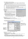
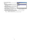
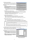
8.7.5 Set-up of floor name and G-50 (Step 4)
Follow these steps to set the G-50A for each floor.
Set floor and G-50A assignments
[Procedure]
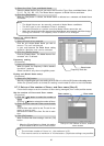
1) Select the G-50A.
In the Floor and G/W Options window, click the
check box of the G-50A to be assigned to each floor.
: Unassigned
: Assigned
Assign a G-50 to every floor. (Up to 5 of G-50A can
be set to each floor.)
2) Click the [OK] button.
When finished with these settings, click the [OK] button.
* When the [Cancel] button is clicked, this setting is
terminated to return to the initial window.
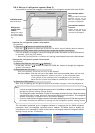
Maintenance Tip
•
When Paint Brush Mode is activated, the file
name and graphic size is set and should no
t
be changed. If changed, the floor plane may
not display correctly.
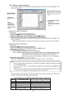
Creation of a plane view screen
Paint Brush window (initial state)
Base plane
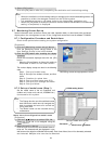
Floor plane
Floor selection
Set-up of floor name and G-50A screen
Check box