


WIRELESS NETWORK IP CAMERA User’s Guide
63
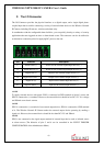
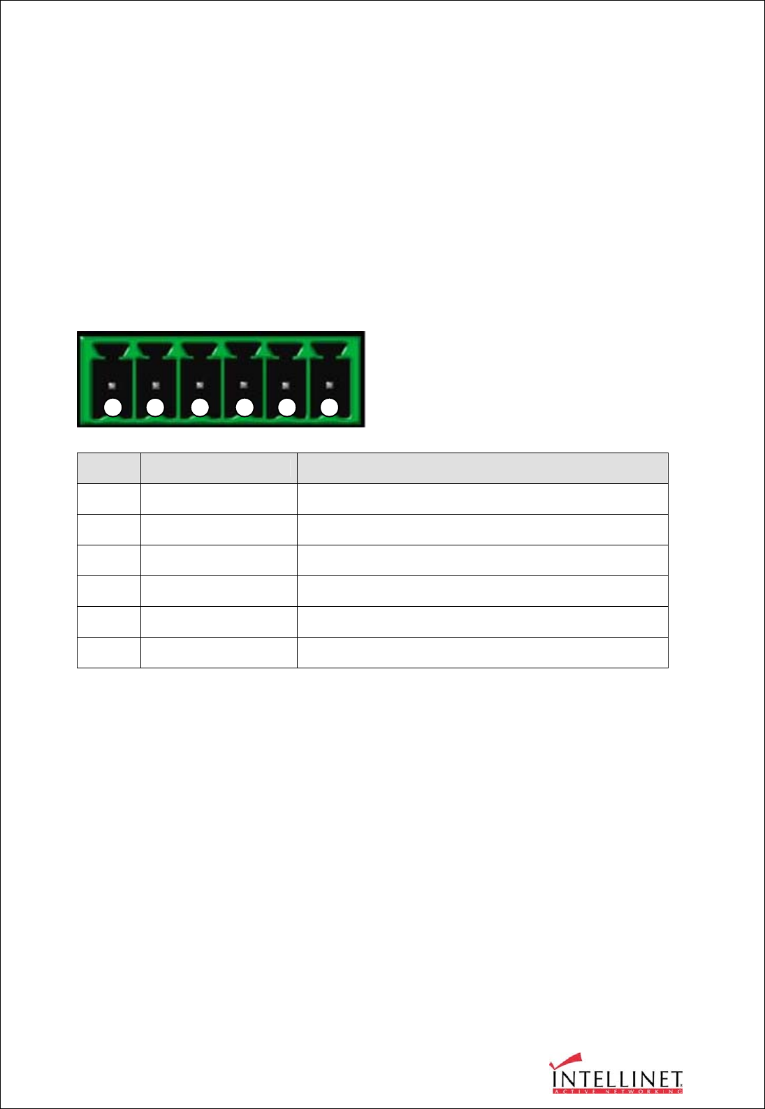
F. The I/O Connector
The I/O Connector provides the physical interface to a digital output, and a single digital photo-
coupled input that is used for connecting a variety of external alarm devices to the Wireless Network
IP Camera; including, IR-sensors, switches and alarm relay.
In combination with the configurable alarm facilities, you can quickly develop a variety of security
applications that are triggered on time- or alarm-based events. The connector can also be utilized as
an alternative connection point for supplying DC power to the unit.
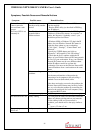
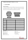
NO Function Description
1
Power GND (-) Power for the external input/output devices (-)
2
Power DC12V (+) Power for the external input/output devices (+)
3
Digital Out (+) Output to the external output devices (+)
4
Digital Out GND (-) Output to the external output devices (-)
5
Digital In (+) Input for the external input devices (+)
6
Digital In GND (-)
Input for the external input devices (-)
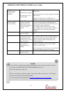
1-2 PIN
To supply external devices with power. PIN1 is connected to GND terminal of device’s power and
PIN2 is connected to (+) terminal. However, the external device should be less DC 12V as a voltage
and 200mA as an electric current.
3-4 PIN
PIN3 is connected to (+) terminal of an external output device; PIN4 is connected to GND terminal
of it. The Wireless Network IP Camera makes the external output device operating by sending a
signal to it.
However, the external device should be less than DC 12V and 200mA.
5-6 PIN
PIN5, 6 are connected to the signal output terminal of external input device such as infrared sensor
or alarm sensor. (The behavior of pins 5 and 6 can be controlled in the EVENT TRIGGER
CONFIGURATION of the Administrator Menu)
1 2 3 4 5 6