


82 Audio Command Center Series Manual — P/N 51889:E1 6/8/2010
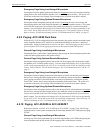
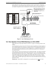
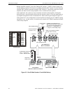
Application Examples One Speaker Circuit With Backup on ACC-25/50
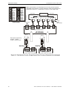
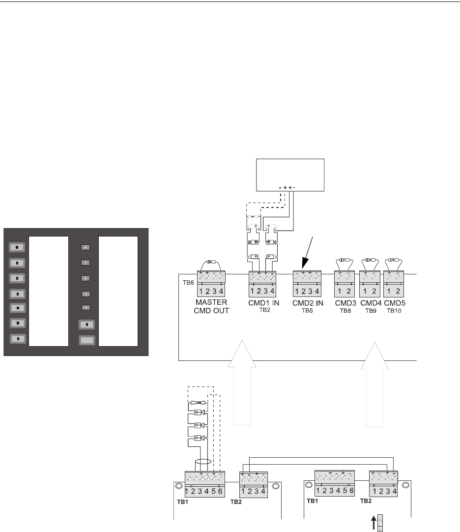
Backup Amplifier switch S1 is set to the ‘Backup ON’ position. 18 AWG or larger jumpers con-
nect the Backup Amplifier TB2 Terminal 3 and Main Amplifier TB2 Terminal 1 as well as Backup
Amplifier TB2 Terminal 4 and Main Amplifier TB2 Terminal 2. Upon failure of the first or main
amplifier, the audio from the backup amplifier will be switched out to the speakers.
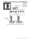
In this application, the system may also be manually activated via the keypad by selecting the
Building Speakers zone push-button followed by the selection of the Fire Message push-button, or
by using the microphone to make an announcement. Refer to the Keypad example in Figure 5.2
In the optional 70.7 V
RMS
configuration, only the amplifier is backed-up; the FC-XRM70 coupling
transformer is not. For this reason, it is not necessary to install an FC-XRM70 transformer module
on the backup amplifier.
Figure 5.2 One 25 Watt Speaker Circuit With Backup
Style Z
FACP ELR Resistor
(for Style Y only)
ACC-25/50 Series
Main Circuit Board
Style Z
Backup
Audio In
Backup
Audio Out
Supervisory
Polarity Shown
a
c
2
5
a
p
p
4
.
w
m
f
Note: Typical illustration of a
Fire•Lite control panel. Refer to the
Command Input Specification in
Section 1.2, ”Specifications” on
page 19, for the voltage range.
ELR Resistor required for
Style Y - Class B only
4.75K, 1 watt P/N:75470
First Amplifier
Mounted on Main Circuit Board
Optional Backup Amplifier
Keypad Example
4.7K ELRs PN: 27072
Make no connections to CMD2
(S5 DIP switch 6 is OFF)
4.7K ELR
Alarm Polarities Shown
Host FACP
NAC
Alarm Polarities Shown
Speaker Backup Speaker Backup
Backup ON
a
c
c
2
5
k
y
b
l
n
k
.
w
m
f
BUILDING
SPEAKERS
FIRE
MESSAGE
POWER ON
SYSTEM
TROUBLE
MESSAGE
TROUBLE
GENERATOR
TONE
GENERATOR
TROUBLE
RECORD
PLAYBACK
TROUBLE
SILENCE
MICROPHONE
TROUBLE