


Audio Command Center Series Manual — P/N 51889:E1 6/8/2010 67
ACC-FFT Answer Call Push-Button (ACC-25/50ZST) Operating Instructions
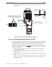
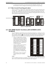
4.3 ACC-FFT Answer Call Push-Button (ACC-25/50ZST)
When a Fire Fighter inserts the FFT Handset (FHS-F) into a remote FFT jack (FPJ-F or RPJ-F), the
Answer Call LED will flash and the piezo will beep. Pressing the Answer Call push-button in this
mode will connect the local FFT Handset with the remote FHS-F. Conversations between the two
locations can be performed by pressing the Push-to-Talk switch on each FFT Handset. To termi-
nate the conversation, unplug the remote FFT Handset (FHS-F) and press the Answer Call push-
button again. Figure 3.15, “ACC-FFT Fire Fighter Telephone Module” on page 55, for additional
information.
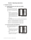
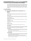
4.4 LED Indicators
4.4.1 LEDs Visible with Backbox Door Closed (Figure 4.1 on
page 63)
Power On
A green LED that remains on while power is within correct limits. If this indicator fails to light
under normal conditions, check for AC and battery power and service the system immediately.
System Trouble
This yellow LED turns on steady to indicate that a fault or abnormal condition exists and that the
ACC-25/50 may be inoperative. Do not allow trouble conditions to remain on the system. Service
the system immediately.
Message Generator Trouble
This yellow LED turns on steady when the supervised digital message generator fails or falls below
acceptable levels.
Tone Generator Trouble
This yellow LED turns on steady when one of the supervised tone generators fail or fall below
acceptable levels.
Microphone Trouble
This yellow LED turns on steady when the supervised microphone connection is open.
Record/Playback
This green LED turns on steady, when the Record/Playback push-button is pressed, to indicate that
the recording process is ready to begin. The LED remains on during recording and turns off when
the Record/Playback push-button is pressed to terminate the recording process
Zone 1/All-Call
• Dual Zone Operation - this two color LED turns green when Zone 1 speaker circuit is activated
by an alarm condition or manually and turns yellow when the push-button is pressed during an
alarm condition to turn off the Zone 1 speaker circuit
• Single Zone Operation - this LED turns green when the push-button is pressed to initiate an
All-Call operation
Zone 2/Audio On/Off
• Dual Zone Operation - this two color LED turns green when Zone 2 speaker circuit is activated
by an alarm condition or manually and turns yellow when the push-button is pressed during an
alarm condition to turn off the Zone 2 speaker circuit
• Single Zone Operation - this two color LED turns green to indicate that audio has been
activated by an alarm condition or manually and turns yellow when the push-button is pressed
during an alarm condition to turn off the audio