


20 Audio Command Center Series Manual — P/N 51889:E1 6/8/2010
Product Description Specifications
Battery (lead acid only) - P10
Maximum Charging Circuit: Normal Flat Charge - 27.6V @ 0.800 amp
Maximum Charger Capacity: 18 Amp Hour battery. (Audio Command Center Series cabinet holds
max. 18 Amp Hour Battery.
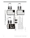
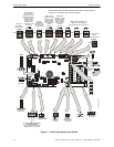
Command Input Circuits (alarm polarities shown)
• CMD1 - TB2 Terminals 3(+) & 4(-) are input terminals and Terminals 1(-) and 2(+) are output
terminals which provide feed through of the NAC circuits to NAC devices down stream
• CMD2 - TB5 Terminals 3(+) & 4(-) are input terminals and Terminals 1(-) and 2(+) are output
terminals which provide feed through of the NAC circuits to NAC devices down stream
• CMD3 - TB8 Terminals 1(+) & 2(-) are input terminals for contact closure only
• CMD4 - TB9 Terminals 1(+) & 2(-) are input terminals for contact closure only
• CMD5 - TB10 Terminals 1(+) & 2(-) are input terminals for contact closure only
Operation: CMD1 & CMD2 circuits are independently field programmable to activate amplifiers
on NAC polarity reversal or contact-closure. IMPORTANT! When CMD1 and CMD2 are config-
ured for reverse polarity, the NAC cannot
be Coded.
CMD3, CMD4 and CMD5 are fixed to activate on contact closure only. End-of-Line resistors must
be connected in all configurations.
Power-limited and supervised circuitry
Normal Operating Voltage Range: 10.5 VDC - 29 VDC; Maximum Voltage: 29 VDC
NAC Reverse Polarity Current (requires End-of-Line Resistor from NAC): 1.6 mA maximum.
Contact Closure Operation Current (requires 4.7K, ½ watt End-of-Line Resistor P/N 27072): 6.6
mA maximum
Maximum Wiring Impedance CMD1 - CMD5 (Contact Closure Operation): 200
Maximum Input Impedance:
• CMD1 & CMD2 (Reverse Polarity Operation): 20K
• CMD1 - CMD5 (Contact Closure Operation): 3.4K
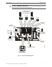
Audio Amplifier Module
Standard ACC-AAM25 Amplifier plugs into P4 of main circuit board, optional ACC-AAM25
Amplifier plugs into P3 of main circuit board
Backup Audio - TB2 [In Terminals 1(+) & 2(-), Out Terminals 3(+) & 4(-)] on Amplifier Module
Operation: When TB2 is wired between the two amplifiers of a panel, the optional amplifier pro-
vides backup to the standard amplifier. Switch S1 on the backup amplifier must be 'ON' and jump-
ers placed from backup amplifier TB2 Terminal 3 to standard amplifier TB2 Terminal 1 and from
backup amplifier TB2 Terminal 4 to standard amplifier TB2 Terminal 2. Refer to Section “One
Speaker Circuit With Backup on ACC-25/50” on page 81, for additional information.
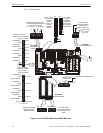
Speaker Circuit - TB1 Terminals 3(+) & 4(-) Style Y, 5(+) & 6(-) Style Z, 1 & 2 Shield (Standby
and Alarm Polarity Shown) on Amplifier Module
Power-limited circuitry
Operation: Circuit can be wired Style Y or Style Z
Normal Operating Voltage: 25 V
RMS
@ 1 amp max. and maximum Load Impedance of 25
(70.7 V
RMS
@ 350 mA max. with maximum Load Impedance of 200operation possible by plug-
ging optional FC-XRM70 conversion module into P1 of audio amplifier).
Circuit wiring is supervised during standby, alarm and when background music is playing
Output Power: 25 watts (20 watts when background music is employed);
Frequency Range: 800Hz - 2,800Hz
Maximum total capacitance for each speaker circuit: 250 µF.
End-of-Line Resistor required for Style Y circuit: 4.75 K, 1 watt (P/N: 75470)