


Audio Command Center Series Manual — P/N 51889:E1 6/8/2010 123
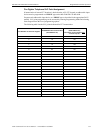
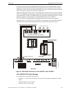
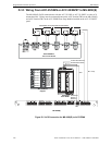
MS-9200(E) Programmed Activation by FACP
In this example, the MS-9200 can route the Fire Evacuation message (message #1) to the activated
audio zones via zone programming. The CMD inputs are not
used to activate the audio panel. The
audio panel defaults to activating the Fire Evacuation voice message.
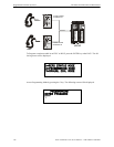
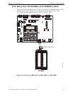
1. Connect ACS wiring from FACP to ACC-25/50ZS/T.
2. Set ACS Address wheels on ACC-ZPMK for address 01.
3. Set DIP switches 1, 2, and 3 on Switch S1 of the ACC-ZPMK for operation with the MS-9200
FACP.
4. Set DIP switches 6, 7, and 8 on Switch S1 of the ACC-ZPMK for the number of
ACC-25/50DAZS panels installed.
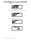
5. Set Switch SW1 on the ACC-ZSM for one or two Audio Amplifier (ACC-AAM25)
configuration.
6. Set Switch SW2 on the ACC-ZSM for Style Y (Class B) or Style Z (Class A) speaker circuit
wiring.
7. Set DIP switches 1, 2, and 3 on Switch S3 of the ACC-25/50ZS/T motherboard for Single
Zone with activation of 2 messages (the second message will not be used).
8. Record a new Fire Evacuation message for message #1, if desired.
9. Enable ACS communication and program zones (32-56) in the MS-9200 FACP,
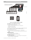
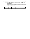
Example #3 - Simultaneous activation of all audio zones with individual control of all voice mes-
sages:
In this example, the MS-9200 simultaneously activates all the audio zones with one of the selected
voice messages. No ACS connection is required and CMD inputs are controlled by modules on the
SLC loop. Upon activation of a CMD input, the audio panel defaults to activating all of the audio
circuits.
1. Connect CMD inputs of the ACC-25/50ZS/T to modules on the SLC loop of the MS-9200
FACP.
2. Set DIP switches 1, 2, and 3 on Switch S1 of the ACC-ZPMK for operation with Non-ACS
FA C P.
3. Set DIP switches 6, 7, and 8 on Switch S1 of the ACC-ZPMK for the number of
ACC-25/50DAZS panels installed.
4. Set Switch SW1 on the ACC-ZSM for one or two Audio Amplifier (ACC-AAM25)
configuration.
5. Set Switch SW2 on the ACC-ZSM for Style Y (Class B) or Style Z (Class A) speaker circuit
wiring.
6. Set DIP switches 1, 2, and 3 on Switch S3 of the ACC-25/50ZS/T motherboard for Single
Zone with activation of 2-5 messages.
7. Record any new messages into the ACC-25/50ZS/T.
8. Program modules on the SLC loop for CMD input activation.