


Audio Command Center Series Manual — P/N 51889:E1 6/8/2010 41
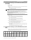
ACC-ZSM Zone Splitter Module (ACC-25/50ZS & ACC-25/50ZST) Field Programming
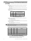
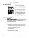
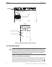
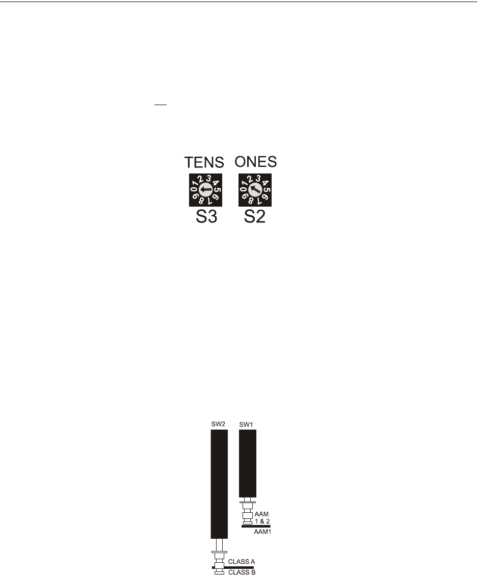
2.8.2 S2 and S3 Addressing Rotary Switches
Two addressing switches are located at the bottom right of the ACC-ZPMK Zone Page Module.
The switches are used to set the ACS (EIA-485) address of the ACC-ZPMK to allow communica-
tion between it and the FACP. This communication link allows the FACP to control speaker zones
under program control.
The ACC-ZPMK must
be set to address 01 to communicate with the FACP. To set the address, use
a small nononductive flat-blade screw driver to turn the switch dial so the arrow points to the cor-
rect address number. The factory default setting is S3 = 0 and S2 = 0. The following illustration
shows the switches set for address 01 with S3 (Tens) set to 0 and S2 (Ones) set to 1.
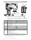
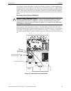
2.9 ACC-ZSM Zone Splitter Module (ACC-25/50ZS & ACC-
25/50ZST)
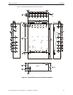
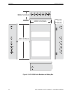
Two switches on the ACC-ZSM Zone Splitter Module are used to configure the speaker circuits
connected to it.
• SW1 - used to configure the circuits for split amplifier application. Setting the switch to the
AAM 1 & 2 position directs the audio from Amplifier 1 to the first two Class A circuits or first
four Class B circuits, and the audio from Amplifier 2 to the next two Class A circuits or next
four Class B circuits. Setting the switch to the AAM1 position sends the audio from Amplifier
1 to all circuits.
• SW2 - used to configure all circuits for Class A (Style Z) or Class B (Style Y) operation.
Figure 2.3 ACC-ZPMK Addressing Switches
a
c
c
z
p
m
a
d
d
.
w
m
f
SW1, which is shown in the AAM 1 & AAM 2
position is set for split amplifier operation.
Note that the factory default setting is AAM1
only for single amplifier operation.
SW2, which is shown in the Class B position,
configures all circuits for Class B (Style Y)
wiring. This is the factory default setting.
a
c
c
z
s
m
s
w
1
.
w
m
f