


68 Audio Command Center Series Manual — P/N 51889:E1 6/8/2010
Operating Instructions LED Indicators
Message 1
This green LED turns on steady to indicate that Message 1 has been activated by an alarm or man-
ually. Note that during the recording process, when the push-button is pressed, the LED will flash
at a ½ second rate to indicate that Message 1 is ready to be recorded. When recording begins, the
LED will turn on steady.
Message 2
This green LED turns on steady to indicate that Message 2 has been activated by an alarm or man-
ually. Note that during the recording process, when the push-button is pressed, the LED will flash
at a ½ second rate to indicate that Message 2 is ready to be recorded. When recording begins, the
LED will turn on steady.
Message 3
This green LED turns on steady to indicate that Message 3 has been activated by an alarm or man-
ually. Note that during the recording process, when the push-button is pressed, the LED will flash
at a ½ second rate to indicate that Message 3 is ready to be recorded. When recording begins, the
LED will turn on steady.
Message 4
This green LED turns on steady to indicate that Message 4 has been activated by an alarm or man-
ually. Note that during the recording process, when the push-button is pressed, the LED will flash
at a ½ second rate to indicate that Message 4 is ready to be recorded. When recording begins, the
LED will turn on steady.
Message 5
This green LED turns on steady to indicate that Message 5 has been activated by an alarm or man-
ually. Note that during the recording process, when the push-button is pressed, the LED will flash
at a ½ second rate to indicate that Message 5 is ready to be recorded. When recording begins, the
LED will turn on steady.
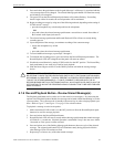
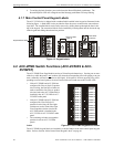
4.4.2 ACC-ZMPK LEDs Visible with Backbox Door Closed (Figure
4.4 on page 66)
FACP Communication
A green LED that remains on when an FACP is connected to the ACC-25/50ZS & ACC-25/50ZST
via the ACS (EIA-485) link from TB1 of the ACC-ZPMK to the ACS terminal on the FACP. If the
LED fails to light, an FACP is not connected or the ACS wiring is faulty. The LED is located in the
top left of the keypad (refer to Figure 4.4 on page 66 for location).
ACC Communication
A green LED that remains on when the ACC-ZPMK is properly communicating with the ACC-
25/50ZS & ACC-25/50ZST main circuit board via the connecting cable. If the LED fails to light,
communication has been lost between the ACC-ZPMK and audio panel. The LED is located in the
top right of the keypad (refer to Figure 4.4 on page 66 for location).
Zone/Circuit Active
A green LED corresponding to each of the 24 circuits on the ACC-ZPMK Zone Page Module. The
LED turns on when the circuit is manually activated by pressing the corresponding key or during an
alarm condition under FACP program control. Pressing the key while the circuit is active will turn
off the circuit and its corresponding LED.