


64 Audio Command Center Series Manual — P/N 51889:E1 6/8/2010
Operating Instructions Switch Functions
4.1.3 RECORD/PLAYBACK
– for recording messages when Record/Bypass switch is in the up Record position (refer to
Sections “S2 - Record Bypass Switch on ACC-25/50 Series Motherboard (ACC-MCB)” on
page 38, Section “S1 DIP Switch Settings on ACC-25/50 Series Motherboard (ACC-
MCB)” on page 36 and Section “S5 DIP Switch Settings on ACC-25/50 Series Motherboard
(ACC-MCB)” on page 37 for additional information on recording messages).
– for reviewing recorded message when Record Bypass Switch is in the down Bypass position
(requires optional FC-LPS module).
4.1.4 TROUBLE SILENCE
– momentary depression silences the local piezo when system is in trouble condition.
4.1.5 Record/Playback Button - Record Customized Messages
The key labeled Record/Playback is used for recording customized messages.
Recording Instructions
Recording a custom message or messages into the ACC-25/50 Series requires that the voice mes-
sage(s) be input via the internal microphone or via the RCA or mini PC Jack. After recording a
new voice message, wait approximately one minute for internal supervision to take place before
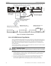
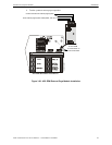
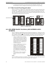
broadcasting the new message over the building speakers. Refer to Figure 2.1 and Figure 2.2 on
page 33 for switch locations.
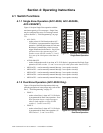
1. Confirm the Message Control settings on S3 DIP switches 1, 2, and 3. These settings will
determine the number of messages that can be recorded and duration of each (refer to Table 2.7
on page 37).
2. The background music feature, which is selected by S5 DIP switch 3, must be disabled
in order
to record a new voice message.
3. Enable recording by setting S5 DIP switch 8 to the ON position. The Record/Playback push-
button is now ready to be used in record operation.
4. Select the record input source by setting S5 DIP switch 7 to the OFF position if recording via
the microphone, or to the ON position if recording via one of the External Audio Input Jacks.
page 19.
5. Slide the Record Bypass switch S2 to the UP position to enable the message storage device.
6. Note the following while recording:
To alert the user that there is only two seconds of record time remaining, the LED on the
Record/Playback push-button will change from steady-on to flashing.
The system Trouble LED and Trouble Relay will be on while recording but the Trouble
Sounder will remain off. The system will not respond to the CMD inputs or Zone activation
buttons while recording
It is not necessary to fill the entire record time. The time limits represent the maximum time
allotted.
Factory default messages are replaced with the custom messages recorded from the External
Audio Input jacks or internal microphone.
7. Press and release the Record/Playback push-button. This will cause the Record/Playback LED
and Message push-button LEDs, as configured by S3 DIP switches 1, 2, and 3 (see Table 2.7
on page 37), to flash on and off. In addition, the panel will indicate a trouble condition since it
cannot be alarm activated.
NOTE: For proper system operation, the voice message length must be at least 8 seconds long.