


Audio Command Center Series Manual — P/N 51889:E1 6/8/2010 39
S4 - Battery Charger Switch on ACC-25/50 Series Motherboard Field Programming
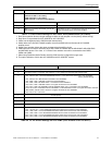
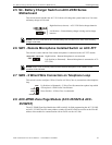
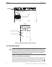
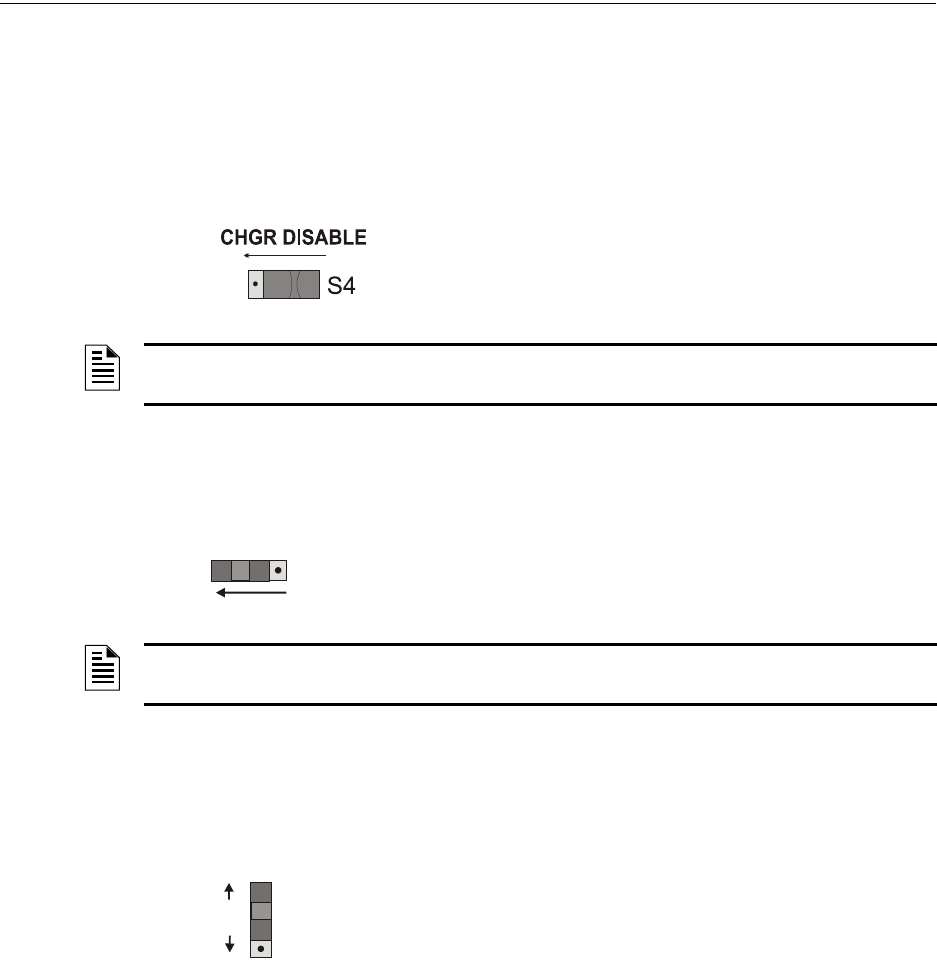
2.5 S4 - Battery Charger Switch on ACC-25/50 Series
Motherboard
This switch controls whether the ACC-25/50 Series will charge the system batteries or if an exter-
nal battery charger will be used.
Right Position (as shown) = ACC-25/50 Series charges batteries.
Left Position = External battery charger is being used to charge
batteries.
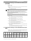
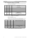
2.6 SW1 - Remote Microphone Installed Switch on ACC-FFT
This switch is used to indicate if the remote microphone is connected to the ACC-FFT module.
Right Position = Remote Microphone is not connected
Left Position (as illustrated) = Remote Microphone is connected to ACC-
FFT (TB1)
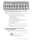
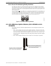
2.7 SW2 - 2 Wire/4 Wire Connection on Telephone Loop
This switch is used to configure 2 Wire (Class B) or 4 Wire (Class A) connections to the telephone
loop.
Up Position (as illustrated) = 2 Wire (Class B) connection to phone loop which
will requires a 4.7K End-of-Line Resistor.
Down Position - 4 Wire (Class A) connection.
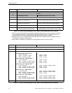
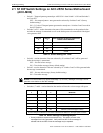
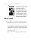
2.8 ACC-ZPMK Zone Page Module (ACC-25/50ZS & ACC-
25/50ZST)
The ACC-ZPMK Zone Page Module has a DIP switch S1 for field programming the ACC-25/50ZS
and ACC-25/50ZST and two rotary address switches S2 and S3 which are used to set the EIA-485
address of the module for communication with an FACP over the ACS link.
a
c
2
5
z
s
s
w
4
.
w
m
f
NOTES: The ACC-25/50 Series still indicates battery fault conditions even when internal battery
charger is not used.
SW1
REMOTE MIC. INSTALLED
NOTES: If SW1 is set to the left position and the Remote Microphone is not installed, a fault
condition will be indicated.
SW2
2 WIRE
4 WIRE
CONNECTION