


58 Audio Command Center Series Manual — P/N 51889:E1 6/8/2010
Installation Installation of Option Modules
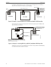
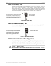
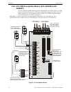
8. Connect field wiring to newly installed amplifier. Refer to Figure 3.12 on page 52 for
illustration of speaker connections if amplifier is being used to expand system power to 50
watts (i.e. providing dual 25 watt speaker circuits). Figure 5.2 on page 82 for illustration of
connections if amplifier is being used as a backup.
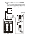
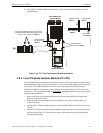
3.8.2 70.7 V
RMS
Transformer Module (FC-XRM70)
The 70.7 V
RMS
Transformer Module can be used to convert the 25 V
RMS
amplifiers for installations
where 70.7 V
RMS
speakers already exist or are to be installed. Speaker wiring continues to be
supervised during standby, alarm and while background music is playing when transformer is
installed. Transformer connector J1 connects to amplifier connector P1.
1. Carefully remove the ACC-AAM25 Audio Amplifier Module(s) from the main circuit board.
Figure 3.17 on page 58 for installation procedures and reverse the steps.
2. Install the three standoffs supplied with the FC-XRM70 Module by inserting each supplied
screw into the three holes on the solder side of the ACC-AAM25 Audio Amplifier Module(s).
Secure each standoff in place with the screws. Refer to Figure 3.18 for the location of the
mounting holes.
3. Reinstall the Audio Amplifier Module(s) following the procedure accompanying Figure 3.17.
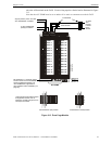
4. Remove the two factory installed jumpers from connector P1 of the Audio Amplifier
Module(s). Refer to the illustration in Figure 3.18.
5. Carefully align the J1 connector on the FC-XRM70 Transformer Module(s) with the P1
connector on the Audio Amplifier Module and press securely into place. Make certain the pins
are properly aligned to prevent bending or breaking of pins.
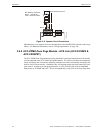
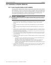
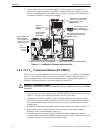
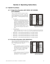
Figure 3.17 Installation of Optional Audio Amplifier
ACC-AAM25 Audio Amplifier
Module - to connector P3 of
the main circuit board
(Steps 4 & 5)
Remove mounting screw and
install supplied Metal Standoff
(Steps 2, 3, & 5)
ACC-AAM25 Audio
Amplifier Module -
factory supplied on
connector P4 of the
main circuit board
Factory installed
metal standoff
(Steps 2 & 5)
Switch S1 -
Backup select
(Step 6)
Factory installed metal standoff (Steps 2 & 5)
Amplifier J1 to main circuit board P3 (Step 4)
Circuit
Trouble
Amp
Supervision
Do not remove jumpers
unless installing FC-
XRM70 Module (Step 7)
a
c
c
2
5
m
t
3
.
w
m
f
!
CAUTION: DISCONNECT POWER
BEFORE INSTALLING ANY MODULES, MAKE CERTAIN ALL POWER (AC AND DC) HAS BEEN
REMOVED.