


Audio Command Center Series Manual — P/N 51889:E1 6/8/2010 53
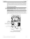
Output Circuits Installation
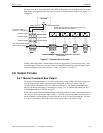
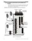
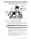
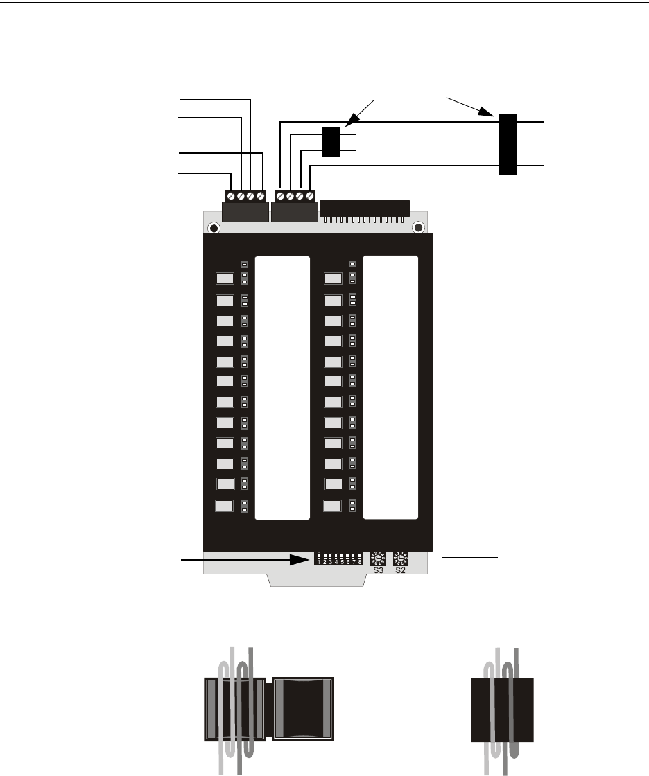
ule to the ACS terminal on the FACP. Circuit wiring requires a ferrite bead as illustrated in Figure
3.13.
Note that the ACC-ZPMK must be set to address 01 in order to communicate with the FACP.
ACC-ZPMK
TB1
TB2
To FACP
ACS Terminal
Address 01
Set S2 = 1
Set S3 = 0
To Other
ACS
Devices
Located
Down
Stream
+
+
--
1 2 3 4
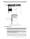
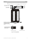
Figure 3.13 Zone Page Module
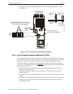
Ferrite Bead
Ferrite Bead in open position
Ferrite Bead in closed position
Large gauge wire should be looped
through bead at least once as
illustrated. Smaller gauge wire can
be looped more often
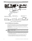
+
+
-
-
Style Z (Class A) return from last
ACC-25/50DAZS, if installed.
To ACC-25/50DAZS
panel(s) if installed
DIP Switches 6, 7 and 8 are used to
set the number of ACC-25/50DAZS
panels installed [see Section 2.8,
”ACC-ZPMK Zone Page Module
(ACC-25/50ZS & ACC-25/50ZST)” on
page 39]
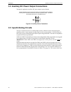
FACP
Zone 1
Zone 2
Zone 3
Zone 4
Zone 5
Zone 6
Zone 7
Zone 8
Zone 9
Zone 10
Zone 11
Zone 12
ACC
Zone 13
Zone 14
Zone 15
Zone 16
Zone 17
Zone 18
Zone 19
Zone 20
Zone 21
Zone 22
Zone 23
Zone 24
a
c
c
z
p
m
b
r
d
.
w
m
f
a
c
c
z
p
m
k
y
p
.
w
m
f
2
5
5
0
f
e
r
r
.
w
m
f