


104 Audio Command Center Series Manual — P/N 51889:E1 6/8/2010
Appendix C: Wiring Requirements
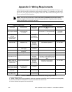
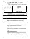
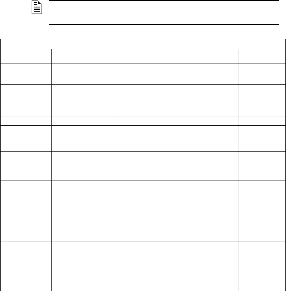
Connecting external system accessories to the AUDIO•COMMAND•CENTER•25/50 Series main
circuits must be carefully considered to ensure proper operation. It is important to use the correct
type of wire, wire gauge and wire run length per each circuit. Refer to the following table to spec-
ify wire requirements and limitations.
NOTE: If an SLC loop is to be run in conduit with AUDIO•COMMAND•CENTER•25/50 Series
Notification Appliance Circuits, the risk of encountering problems can be greatly reduced by using
twisted, shielded cable on the SLC and NACs.
CIRCUIT CONNECTIONS WIRE REQUIREMENTS
Circuit Type Circuit Function
Wire Type &
Limitations
Recommended Maximum Distance
(Feet)
Wire Gauge
AC Power
TB3 (nonpower-limited)
Primary Power Input to
ACC-25/50 Series,
AC Voltage
See Note
1
Power Supplied must be:
120 VAC, 60 Hz, 1.5 amps (see Note
1
)
Terminals Support
12-18 AWG
(see Note
1
)
Audio Output
ACC-AAM25 Module
TB1 and
ACC-ZSM Module
(power-limited)
Notification Appliance Circuit See Note
2
Untwisted,
unshielded or
twisted, shielded
See Note
3
12 - 18 AWG
ACC-ZPMK Module ACS (EIA-485 Circuit 4,000 feet 12 - 18 AWG
ACC-FFT TB1 Telephone Loop See Note
2
Untwisted
unshielded or
twisted, shielded
54 maximum impedance 12 - 18 AWG
ACC-FFT TB2 Contact Closure
Input Trigger
Untwisted
unshielded
54 maximum impedance 12 - 18 AWG
ACC-FFT TB3 Remote Microphone
Connection
4
See Note
4
See Note
4
See Note
4
ACC-EPM Module External Page Connection 12 - 18 AWG
CMD1 and CMD2 Main
Board TB2 and TB5
Triggers ACC-25/50 Series See Note
1
Untwisted,
unshielded or
twisted, shielded
Depends on Output (trigger) Circuit
9 - 32 VDC, 1.6 mA for polarity reversal
relay must be rated at 0.5 amp, 24
VDC
12 - 18 AWG
CMD3, CMD4 and
CMD5 Main Board TB8,
TB9 and TB10
Triggers ACC-25/50 Series See Note
1
Untwisted,
unshielded or
twisted, shielded
Depends on Output (trigger)
Circuit from contact device
12 - 18 AWG
Main Board TB6 Master
Command Bus Reverse
Polarity (power-limited)
Output Trigger for Multiple
ACC-25/50 Series
configurations
Untwisted,
unshielded
200 ohms maximum 12 - 18 AWG
Trouble Relay Main
Board TB1
Trouble Output Maximum
Current 2 amps
Depends on Input Circuit 12 - 18 AWG
AC Loss Relay
Main Board TB7
AC Loss Output Maximum
Current 2 amps
Depends on Input Circuit 12 - 18 AWG
Table C.1 AUDIO•COMMAND•CENTER•25/50 Series Wiring Requirements
1 Refer to NEC Standards.
2 Twisted, shielded wire is recommended for maximum protection against EMI and AFI emissions and susceptibility.
3 Must also meet NFPA 72 Standards for minimum and maximum sound levels.
4 Refer to Remote Microphone Document #51247.