


26 Audio Command Center Series Manual — P/N 51889:E1 6/8/2010
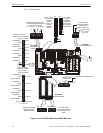
Product Description Circuits
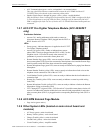
• Amplifier Supervision (green) - Amplifier module
1.4 Circuits
Input Circuits - CMD1, CMD2, CMD3, CMD4 & CMD5
• Input circuits CMD1 and CMD2 are independently field programmable to accept Notification
Appliance Circuits or normally open contacts. (IMPORTANT! When CMD1 and CMD2 are
configured for reverse polarity, the NAC cannot
be Coded). Terminals are provided to allow
feed-through of the NACs, allowing placement of the ACC-25/50 Series anywhere along a
Notification Appliance Circuit. A trouble on the ACC-25/50 Series will cause relay contacts at
the out terminals of CMD1 to open, causing an NAC circuit trouble at the FACP.
• Programming CMD1 and/or CMD2 for activation on contact closure will allow activation of
the amplifiers on a normally open contact transfer to the closed condition. Contact wiring is
supervised for open conditions. A short will cause amplifier activation (contact closure).
• Input circuits CMD3, CMD4 and CMD5 will only activate on contact closure which will allow
activation of the amplifiers on a normally open contact transfer to the closed condition.
Contact wiring is supervised for open conditions.
Audio Input Jacks
• RCA Jack provides convenient connection to an audio source such as a tape player for
recording a new digital message. It may also be used for background music if approved by
local AHJ. Background music is prohibited during AC loss conditions to preserve battery
power.
• PC Jack provides convenient connection to an audio source such as a personal computer for
recording a new digital message. The jack allows vertical plug-in of a standard mini-jack
cable. It may also be used for background music if approved by local AHJ. Background music
is prohibited during AC loss conditions to preserve battery power.
Output Circuits
• Specific Application Power Output, 35 mA @ 24 VDC.
• Main circuit provides a 24 Volt Battery Charger (up to 18 AH batteries) @ 800 mA maximum.
Master Command Output Bus
• Normal Operating Voltage: 24 VDC regulated, filtered. Reverse Polarity Current 120 mA
maximum
• Output reverses polarity on activation
• All-Call Paging control bus for the Audio Command Center Distributed Audio panel (ACC-
25/50DA) or other Fire•Lite UL-listed audio products
Notification Appliance Circuit
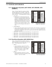
• One NAC Speaker Circuit Style Y or Style Z with each ACC-AAM25 amplifier module.
• Four NAC Speaker Circuits Style Z or eight Style Y with ACC-ZSM (ACC-25/50ZS/T only)
Relays
• One Form-C Trouble Relay. Contacts are rated 2.0 amps @ 30 VDC (resistive) and 0.6 amps
@ 30 VAC (resistive)
NOTE: The ACC-25/50 Series will not open the out terminals while in alarm or during AC loss if
the Trouble Relay is programmed not to transfer on AC Loss conditions (refer to Switch 8 in Table
2.3 on page 34). Monitoring ACC-25/50 Series troubles while in alarm requires use of
independent trouble relay at TB1.