


Audio Command Center Series Manual — P/N 51889:E1 6/8/2010 19
Specifications Product Description
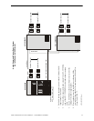
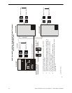
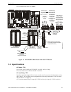
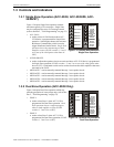
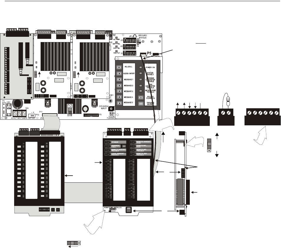
ACC-25/50ZST with ACC-FFT Module
1.2 Specifications
AC Power - TB3
ACC-25/50, ACC-25/50ZS, ACC-25/50ZST: 120 VAC, 60 Hz, 1.5 amp.
Wire size: minimum #14 AWGb with 600 V insulation.
AC Loss Relay - TB7
Operation: normally energized fail-safe relay transfers on AC power loss for independent monitor-
ing by DACT. AC Loss Relay can be programmed to be the only indication of an AC loss condi-
tion (see Table 2.3 on page 34).
AC Loss relay contact rating: 2.0 amps @ 30 VDC (resistive), 0.6 amps @ 30 VAC (resistive)
TB1 TB2
P1
SW1
BACK-UP ON
CKT TBL
AMP SUPV
J1
TB1 TB2
P1
SW1
BACK-UP ON
CKT TBL
AMP SUPV
J1
1 2 3 4 5 6 7 8
ON
S1
ON
S3
0
5
4
3
2
1
9
8
7
6
0
5
4
3
2
1
9
8
7
6
S2
TENS
ONES
AAM
1 & 2
AAM1
JP1
TB1
TB9
TB4
SW2
SW1
TB5
TB6
CLASS A
CLASS B
SW1
J1
TB1
TB2
TB3
FFT 1
FFT 2
FFT 3
FFT 4
FFT 5
FFT 6
FFT 7
FFT 8
FFT 9
FFT 10
FFT 11
FFT 12
FFT 13
FFT 14
FFT 15
FFT 16
FFT 17
FFT 18
FFT 19
FFT 20
FFT 21
FFT 22
FFT 23
FFT 24
SW1
TB1
TB2
TB3
J3
J2
J1
1 2 3 4 5 6
1 2 3 4 5 6
1 2
SW2
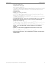
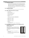
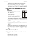
Figure 1.4 ACC-25/50ZST Main Board with ACC-FFT Module
AC25ZSTMNTa.wmf
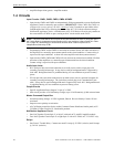
Dark stripe on
ribbon cable must
be positioned to
left as shown!!
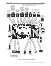
Remote
Microphone
Wiring
Power
Grnd
+ Audio
- Audio
Earth
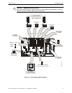
Remote Page
Jack Keyswitch
used for All-Call
Phone Paging
(4.7K ELR
required after
last RPJ
Keyswitch or at
TB2 if
Keyswitch is
not used)
Class A Class B
Return Out
+ shld - + shld -
Audio Wiring to
Remote Page
Jack (4.7K ELR
required after last
RPJ for Class B
wiring only)
switch position
shown for
2-wire Class B
telephone
connection
2-wire
4-wire
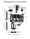
(ribbon cable is required when
annunciating remote Fire Fighter
Telephone locations)
to P5
on
main
board
Panel FFT
Handset
Connector
(side view)
Fire Fighter
Telephone Module
REMOTE MIC INSTALLED
switch position shown
for remote
microphone installed
Zone Page Module
Ribbon
Cable from
J3 on back
of
to P4 on
back of