


38 Audio Command Center Series Manual — P/N 51889:E1 6/8/2010
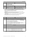
Field Programming S2 - Record Bypass Switch on ACC-25/50 Series Motherboard (ACC-MCB)
• Switch 4 - used in conjunction with Switch 5 to select AC Loss Delay time.
• Switch 5 - used in conjunction with Switch 4 to select AC Loss Delay time:
4 OFF and 5 OFF = No AC Loss Delay - immediate reporting (factory default)
4 OFF and 5 ON = 6 hour delay
4 ON and 5 OFF = 2 hour delay
4 ON and 5 ON = not used (invalid setting)
• Switch 6 - used for All-Call Paging from Remote Microphone
OFF = disable All-Call paging during page from Remote Microphone (factory default
setting)
ON = enable All-Call paging during page from Remote Microphone
• Switch 7 - used to select audio panel configuration
OFF = ACC-25/50 or ACC-25/50ZS
ON = ACC-25/50ZST
• Switch 8 - used to enable/disable transferring of Trouble Relay/CMD1 trouble contacts during
AC loss
OFF = CMD1 & Trouble Relay contacts track the AC Loss Relay and transfer upon AC
loss condition
ON = Only the AC Loss Relay contacts will transfer upon AC loss condition
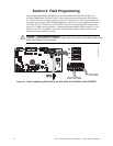
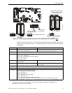
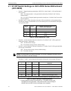
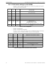
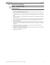
2.4 S2 - Record Bypass Switch on ACC-25/50 Series
Motherboard (ACC-MCB)
This switch, when placed in the down position, prevents accidental erasure of stored voice mes-
sages. See “Record/Playback Button - Record Customized Messages” on page 64 for additional
information.
UP Position = The stored digital voice message may be overwritten with
a new one.
Down Position = The stored digital voice message can not be
overwritten (factory default setting).
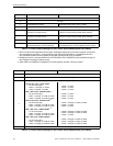
OFF ON OFF Single
Zone
20 sec. Message 1 to
AAM1 & 2
Message 2 to
AAM1 & 2
Message 3 to
AAM1 & 2
not used not used
ON ON OFF Single
Zone
15 sec.
5
Message 1 to
AAM1 & 2
Message 2 to
AAM1 & 2
Message 3 to
AAM1 & 2
Message 4 to
AAM1 & 2
not used
ON OFF ON Single
Zone
12 sec.
5
Message 1 to
AAM1 & 2
Message 2 to
AAM1 & 2
Message 3 to
AAM1 & 2
Message 4 to
AAM1 & 2
Message 5 to
AAM1 & 2
1 CMD1 has the highest priority, CMD5 has the lowest priority.
2 Dual Zone operation directs a single message to either or both amplifier circuits (factory default setting)
3 AAM1 refers to the first ACC-AAM25 amplifier circuit and AAM2 refers to the second ACC-AAM25 amplifier
circuit.
4 Single Zone operation directs the same message to both amplifier circuits.
5 The factory default evacuation message (length = 17 seconds) must be re-recorded to fit into this time slot.
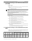
Switch
1
Switch
2
Switch
3
Mode
Maximum
Length of
Each
Message
Audio Signal Control
CMD1
1
CMD2 CMD3 CMD4 CMD5
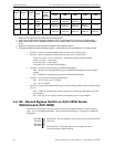
Table 2.7 Switch Settings for Message Control
RECORD
BYPASS
RECORD
BYPASS
2
5
5
0
b
y
p
s
.
w
m
f