


DMC-1700/1800 Chapter 5 Command Basics • 81
Binary Command Format
All binary commands have a 4 byte header and is followed by data fields. The 4 bytes are specified in hexadecimal
format.
Header Format:
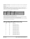
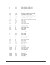
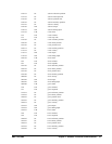
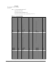
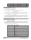
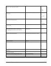
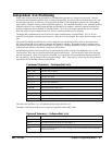
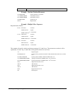
Byte 1 specifies the command number between 80 to FF. The complete binary command number table is listed
below.
Byte 2 specifies the # of bytes in each field as 0,1,2,4 or 6 as follows:
00 No datafields (i.e. SH or BG)
01 One byte per field
02 One word (2 bytes per field)
04 One long word (4 bytes) per field
06 Galil real format (4 bytes integer and 2 bytes fraction)
Byte 3 specifies whether the command applies to a coordinated move as follows:
00 No coordinated motion movement
01 Coordinated motion movement
For example, the command STS designates motion to stop on a vector move, S coordinate system. The third byte
for the equivalent binary command would be 01.
Byte 4 specifies the axis # or data field as follows
Bit 7 = H axis or 8
th
data field
Bit 6 = G axis or 7
th
data field
Bit 5 = F axis or 6
th
data field
Bit 4 = E axis or 5
th
data field
Bit 3 = D axis or 4
th
data field
Bit 2 = C axis or 3
rd
data field
Bit 1 = B axis or 2
nd
data field
Bit 0 = A axis or 1
st
data field
Datafields Format
Datafields must be consistent with the format byte and the axes byte. For example, the command PR 1000,, -500
would be
A7 02 00 05 03 E8 FE 0C
where A7 is the command number for PR
02 specifies 2 bytes for each data field
00 S is not active for PR
05 specifies bit 0 is active for A axis and bit 2 is active for C axis (2
0
+ 2
2
=5)
03 E8 represents 1000
FE OC represents -500