


DMC-1700/1800 Chapter 1 Overview • 3
WATCHDOG TIMER
68331
MICROCOMPUTER
WITH
4 Meg RAM
4 Meg FLASH EEPROM
HIGH-SPEED
MOTOR/ENCODER
INTERFACE
FOR
X,Y,Z,W, etc.
I/O INTERFACE
DMA/DPRAM
2ND FIFO
Primary
FIFOS
ISA/PCI BUS
8 UNCOMMITTED
ANALOG INPUTS
HIGH-SPEED LATCH FOR EACH AXIS
8 PROGRAMMABLE,
OPTOISOLATED
INPUTS
8 PROGRAMMABLE
OUTPUTS
ISOLATED LIMITS AND
HOME INPUTS
MAIN ENCODERS
AUXILIARY ENCODERS
+/- 10 VOLT OUTPUT FOR
SERVO MOTORS
PULSE/DIRECTION OUTPUT
FOR STEP MOTORS
HIGH SPEED ENCODER
COMPARE OUTPUT
Interrupts
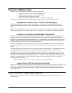
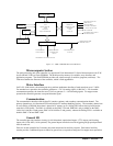
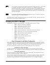
Figure 1.1 - DMC-1700/1800 Functional Elements
Microcomputer Section
The main processing unit of the controller is a specialized 32-bit Motorola 68331 Series Microcomputer with 512K
byte RAM and 512K byte Flash EEPROM. The RAM provides memory for variables, array elements, and
application programs. The flash EEPROM provides non-volatile storage of variables, programs, and arrays. The
Flash also contains the firmware of the controller, which is field upgradeable.
Motor Interface
Galil’s GL-1800 custom, sub-micron gate array performs quadrature decoding of each encoder at up to 12 MHz.
For standard servo operation, the controller generates a +/-10 Volt analog signal (16 Bit DAC). For sinusoidal
commutation operation, the controller uses 2 DACs to generate 2
+/-10Volt analog signals. For stepper motor
operation the controller generates a step and direction signal.
Communication
The communication interface with the host PC contains a primary and secondary communication channel. The
primary channel uses a bi-directional FIFO and includes PC interrupt handling circuitry. The secondary channel can
be set as DMA or DPRAM where data is placed in PC memory or as a Polling FIFO where data is placed into the
controller’s FIFO buffer. The DMA is available on the DMC-1700 and, DPRAM is only available on the DMC-
1800 (1810-1840 Rev H and greater, DMC-1850-1880 Rev E and greater), whereas the Polling FIFO is available on
both the DMC-1700 and DMC-1800.
General I/O
The controller provides interface circuitry for 8 bi-directional, optoisolated inputs, 8 TTL outputs, and 8 analog
inputs with 12-Bit ADC (16-bit optional). The general inputs can also be used for triggering a high-speed positional
latch for each axis.
Each axis on the controller has 2 encoders, the main encoder and an auxiliary encoder. Each unused auxiliary
encoder provides 2 additional inputs available for general use (except when configured for stepper motor operation).