


DMC-1700/1800 Chapter 2 Getting Started • 11
standard servo axes and one axis of sinusoidal commutation, the controller will require a total of four DAC’s and the
controller must be a DMC-1740 or DMC-1840.
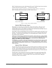
Sinusoidal commutation is configured with the command, BA. For example, BAX sets the X axis to be sinusoidally
commutated. The second DAC for the sinusoidal signal will be the highest available DAC on the controller. For
example: Using a DMC-1740, the command BAX will configure the X axis to be the main sinusoidal signal and the
‘W’ axis to be the second sinusoidal signal.
The BA command also reconfigures the controller to indicate that the controller has one less axis of ‘standard’
control for each axis of sinusoidal commutation. For example, if the command BAX is given to a DMC-1740
controller, the controller will be re-configured to a DMC-1730 controller. By definition, a DMC-1730 controls 3
axes: X,Y and Z. The ‘W’ axis is no longer available since the output DAC is being used for sinusoidal
commutation.
Further instruction for sinusoidal commutation connections are discussed in Step 6.
Stepper Motor Operation:
To configure the DMC-1700/1800 for stepper motor operation, the controller requires a jumper for each stepper
motor and the command, MT, must be given. The installation of the stepper motor jumper is discussed in the
following section entitled “Installing Jumpers on the DMC-1700/1800”. Further instruction for stepper motor
connections are discussed in Step 8c.
Step 2. Install Jumpers on the DMC-1700/1800
Master Reset and Upgrade Jumpers
JP1 contains two jumpers, MRST and UPGRD. The MRST jumper is the Master Reset jumper. With
MRST connected, the controller will perform a master reset upon PC power up or upon the reset input
going low. Whenever the controller has a master reset, all programs, arrays, variables, and motion
control parameters stored in EEPROM will be ERASED.
The UPGRD jumper enables the user to unconditionally update the controller’s firmware. This jumper
is not necessary for firmware updates when the controller is operating normally, but may be necessary
in cases of corrupted EEPROM. EEPROM corruption should never occur, however, it is possible if
there is a power fault during a firmware update. If EEPROM corruption occurs, your controller may
not operate properly. In this case, install the UPGRD Jumper and use the update firmware function on
the Galil Terminal to re-load the system firmware.
Opto Isolation Jumpers
The inputs and limit switches are optoisolated. If you are not using an isolated supply, the internal
+5V supply from the PC may be used to power the optoisolators. This is done by installing jumpers on
JP3 and/or JP13.
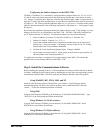
Stepper Motor Jumpers
For each axis that will be used for stepper motor operation, the corresponding stepper mode (SM)
jumper must be connected. The stepper motor jumpers, labeled JP5 for axes X through W and JP4 for
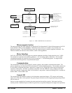
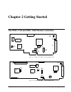
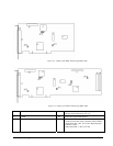
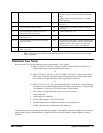
axes E through H, are located directly beside the GL-1800 IC’s on the main board (see the diagram for
the DMC-1700/1800). The individual jumpers are labeled SMX, SMY, SMZ and SMW for axes 1
through 4 and SME, SMF, SMG and SMH for axes 5 through 8.
(Optional) DMA Jumpers
The DMA channel is only available with the DMC-1700 controller. The DMC-1700 controller allows
either DMA channel 0 or 1 to be selected. The jumper location JP4 on the DMC-1740 and JP6 on the