


DMC-1700/1800 Chapter 4 - Software Tools and Communications • 71
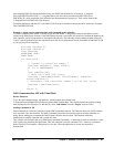
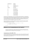
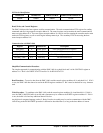
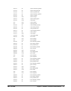
PCI Device Identification
DEVICE ID VENDOR ID SUBSYSTEM ID SUBSYSTEM VENDOR ID
9050H 10B5H 1800H 1079H
Read, Write, and Control Registers
The DMC-1800 provides four registers used for communication. The main communications FIFO register for sending
commands and receiving responses occupies address N. The control register used to monitor the main communications
status occupies address N+4. The reset register occupies address N+8 and is used for resetting the controller and/or main
read/write FIFO registers as well as retrieving the interrupt status byte. The secondary FIFO for accessing the data
record occupies address N+C.
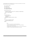
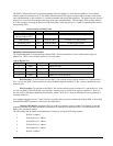
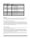
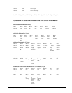
Communication with DMC-1800
Register Address Read/Write Description
Main FIFO N Read / Write
Send commands and receive responses
CONTROL N+4 Read / Write For FIFO status control
IRQ / RESET N+8 Read / Write For IRQ status byte and controller reset
Secondary FIFO N+C Read only For data record access
Simplified Communication Procedure
The simplest approach for communicating with the DMC-1800 is to check bits 0 and 2 of the CONTROL register at
address N+4. Bit 0 is for WRITE STATUS and bit 2 is for READ STATUS.
Read Procedure - To receive data from the DMC-1800, read the control register at address N+4 and check bit 2. If bit 2
is zero, the DMC-1800 has data to be read in the READ register at address N. Bit 2 must be checked for every character
read.
Write Procedure - To send data to the DMC-1800, read the control register at address N+4 and check bit 0. If bit 0 is
zero, the DMC-1800 FIFO buffer is not full and a character may be written to the WRITE register at address N. If bit 0
is one, the buffer is full and any additional data will be lost.
Any high-level computer language such as C, Basic, Pascal or Assembly may be used to communicate with the DMC-
1800 as long as the READ/WRITE procedure is followed as described above, so long as the base address is known.