


126 • Chapter 6 Programming Motion DMC-1700/1800
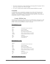
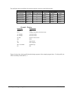
V1= _DEX
The command, TD XYZW, returns the current position of the auxiliary encoder.
The command, DV 1,1,1,1, configures the auxiliary encoder to be used for backlash compensation.
Backlash Compensation
There are two methods for backlash compensation using the auxiliary encoders:
1. Continuous dual loop
2. Sampled dual loop
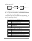
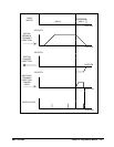
To illustrate the problem, consider a situation in which the coupling between the motor and the load has a backlash.
To compensate for the backlash, position encoders are mounted on both the motor and the load.
The continuous dual loop combines the two feedback signals to achieve stability. This method requires careful
system tuning, and depends on the magnitude of the backlash. However, once successful, this method compensates
for the backlash continuously.
The second method, the sampled dual loop, reads the load encoder only at the end point and performs a correction.
This method is independent of the size of the backlash. However, it is effective only in point-to-point motion
systems which require position accuracy only at the endpoint.
Continuous Dual Loop - Example
Connect the load encoder to the main encoder port and connect the motor encoder to the dual encoder port. The
dual loop method splits the filter function between the two encoders. It applies the KP (proportional) and KI
(integral) terms to the position error, based on the load encoder, and applies the KD (derivative) term to the motor
encoder. This method results in a stable system.
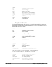
The dual loop method is activated with the instruction DV (Dual Velocity), where
DV 1,1,1,1
activates the dual loop for the four axes and
DV 0,0,0,0
disables the dual loop.
Note that the dual loop compensation depends on the backlash magnitude, and in extreme cases will
not stabilize the loop. The proposed compensation procedure is to start with KP=0, KI=0 and to
maximize the value of KD under the condition DV1. Once KD is found, increase KP gradually to a
maximum value, and finally, increase KI, if necessary.
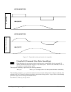
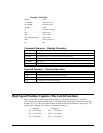
Sampled Dual Loop - Example
In this example, we consider a linear slide which is run by a rotary motor via a lead screw. Since the lead screw has
a backlash, it is necessary to use a linear encoder to monitor the position of the slide. For stability reasons, it is best
to use a rotary encoder on the motor.
Connect the rotary encoder to the X-axis and connect the linear encoder to the auxiliary encoder of X. Assume that
the required motion distance is one inch, and that this corresponds to 40,000 counts of the rotary encoder and 10,000
counts of the linear encoder.
The design approach is to drive the motor a distance, which corresponds to 40,000 rotary counts. Once the motion is
complete, the controller monitors the position of the linear encoder and performs position corrections.
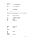
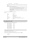
This is done by the following program.
INSTRUCTION INTERPRETATION
#DUALOOP Label
CE 0 Configure encoder
DE0 Set initial value