


DMC-1700/1800 Appendices • 203
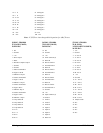
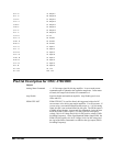
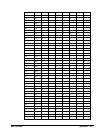
29 I+ E 79 Output 9
30 I- E 80 Output 10
31 A+ F 81 Output 11
32 A- F 82 Output 12
33 B+ F 83 Output 13
34 B- F 84 Output 14
35 I+ F 85 Output 15
36 I- F 86 Output 16
37 A+ G 87 +5V
38 A- G 88 Ground
39 B+ G 89 Ground
40 B- G 90 Ground
41 I+ G 91 Input 17
42 I- G 92 Input 18
43 A+ H 93 Input 19
44 A- H 94 Input 20
45 B+ H 95 Input 21
46 B- H 96 Input 22
47 I+ H 97 Input 23
48 I- H 98 Input 24
49 +12V 99 -12V
50 +12V 100 -12V
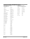
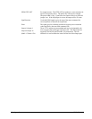
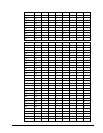
Pin-Out Description for DMC-1700/1800
Outputs
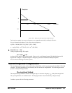
Analog Motor Command +/- 10 Volt range signal for driving amplifier. In servo mode, motor
command output is updated at the controller sample rate. In the motor
off mode, this output is held at the OF command level.
Amp Enable Signal to disable and enable an amplifier. Amp Enable goes low on
Abort and OE1.
PWM/STEP OUT PWM/STEP OUT is used for directly driving power bridges for DC
servo motors or for driving step motor amplifiers. For servo motors: I
f
you are using a conventional amplifier that accepts a +/-10 Volt analog
signal, this pin is not used and should be left open. The PWM output is
available in two formats: Inverter and Sign Magnitude. In the Inverter
mode, the PWM (25kHz) signal is .2% duty cycle for full negative
voltage, 50% for 0 Voltage and 99.8% for full positive voltage (25kHz
Switching Frequency). In the Sign Magnitude Mode (Jumper SM), the
PWM (50 kHz) signal is 0% for 0 Voltage, 99.6% for full voltage and
the sign of the Motor Command is available at the sign output (50kHz
Switching Frequency).