


72 • Chapter 4 - Software Tools and Communications DMC-1700/1800
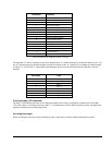
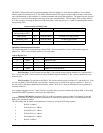
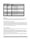
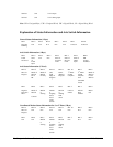
FIFO Control Register at N+4
Status Bit Read/Write Meaning
7 Read Only If 1, Secondary FIFO empty
6 Read/Write IRQ enable: Write 1 to enable IRQ
Write 0 to disable IRQ
Read 1 = IRQ enabled
5 Read/Write IRQ status: Write 1 to clear IRQ
Read 1 = IRQ pending
4 Read/Write Freeze Status of Secondary FIFO:
Write 1 to freeze 2
nd
FIFO
Write 0 to clear freeze of 2
nd
FIFO
Read 1 = 2
nd
FIFO frozen
3 Read Only If 1, Secondary FIFO is busy updating
2 Read Only If 1, DMC to PC Buffer empty, No data to be read
1 Read Only
If 0, PC to DMC buffer not half full. Can write at least 255 bytes.
If 1, buffer is more than half full.
0 Read Only If 1, PC to DMC Buffer full, Do not write data
Half Full Flag
The Half Full flag (Bit 1 of the control register) can be used to increase the speed of writing large blocks of data to the
controller. When the half full bit is zero, the write buffer is less than half full. In this case, up to 255 bytes can be
written to the controller at address N without checking the buffer full status (bit 0 of the control register).
Reading the Data Record from the Secondary FIFO
To read the data record from the secondary FIFO, first the “freeze” bit (bit 4 of N+4) of the control register must be set,
Then wait for the controller to finish updating the data record by monitoring the “busy status bit (bit3 of N+4), when bit
3 is “0” the data record can be read. Since the Secondary FIFO at N+C is 4 bytes wide, data may be read in 1 byte, 2 byte
or 4 byte increments. Read the data at N+C until bit 7 of N+4 is 1, signifying that the FIFO is empty. After the data has
been read, un-freeze the secondary FIFO by setting bit 4 of N+4 to “0”, which allows the controller to continue to refresh
the data record at the defined rate specified by the DR command.
Enabling and Reading IRQ’s
In order to service interrupts from the IRQ line, the IRQ control register (Status Byte) must first be enabled. This is done
by setting bit 6 of the control register (N+4) equal to “1”.
When interrupted, a device driver’s interrupt service routine must verify that the interrupt originated from the DMC-
1800 controller. This is done by checking that the IRQ enable and IRQ status bits (bit 5 and 6 of N+4) are high. The
Status Byte can then be read by reading the register at N+8. The returned Status Byte indicates what event generated the
interrupt (for more information on specific interrupt events, see the EI and UI commands in the Command Reference or
the previous section “Controller Event Interrupts…” in this chapter).
Once the Status Byte has been read, the interrupt must be cleared by writing a “1” to bit-5 of N+4. Note: to preserve
values of other bits, the interrupt service routine should read N+4, set bit 5, and write this value back to N+4 to clear the
interrupt.