


DMC-1700/1800 Chapter 4 - Software Tools and Communications • 69
It is a good idea to clear the FIFO pointer register before attempting this procedure. Send a no-op instruction, by
reading N+1 address, before you start. Note: Clearing the FIFO will also reset the configuration for the interrupt
mask register. Refer to “Interrupt Service for the DMC-1700” below for re-enabling the IRQ.
Interrupt Service for the DMC-1700
The hardware interrupt line (IRQ) provides a mechanism for the controller to alert the host application of certain
events. This alleviates the need to continually poll the controller for status using the main FIFO. When servicing the
interrupt, a status byte is retrieved with a specific event designator. Refer to the previous section “Controller Event
Interrupts…” in this chapter for a complete list of the events and conditions.
Before an interrupt can be received, the interrupt register on the FIFO chip (MailBox) must first be configured and
enabled. Also, a valid IRQ line must be selected (refer to Ch.2 for proper jumper settings for IRQ). Assuming a
valid IRQ line has been selected, the following procedure outlines the steps needed to configure, enable, and service
the interrupt.
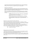
1. Configure the FIFO interrupt register by writing a 2 and then a 4 to N+1. This configures the
FIFO chip for mailbox interrupt. Note: this must be done any time after clearing the FIFO,
because clearing the FIFO also clears this configuration.
2. Enable the interrupt by writing a 6 to N+1 then reading back from N+1. This effectively
clears the interrupt register and signals the firmware that the FIFO is ready for interrupts.
3. Upon interrupt, Service the interrupt by writing a 6 to N+1 then reading back from N+1. The
returned status byte from N+1 will then contain the event designator that initiated the
interrupt.
Data Record access using Secondary FIFO or DMA for the DMC-1700
The DMC-1700 controller provides either a secondary FIFO or Direct Memory Access (DMA) for accessing the
controller’s data record. The DMA channel can be selected as either channel 0 or 1 as described in Ch.2. The data record
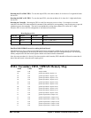
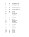
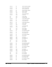
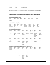
is up to a 256 byte binary data file that contains controller information such as position, error, I/O status, etc. A complete
memory map and explanation of the data record is given at the end of this chapter.
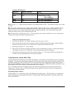
The DRn command sets the mode (Polling FIFO or DMA) and the rate at which the data record is updated in the
controller registers. The argument “n” specifies the rate as 2
n
sample periods, or 2
n
ms (the sample period is 1ms at the
default servo rate of TM1000) and has an integer range of 0 to 8, where 0 turns the data record off. Use a negative “n”
value to set the mode for secondary FIFO, and a positive “n” for DMA access. For example:
DR-2 Sets secondary polling FIFO access at 4ms update
DR1 Sets DMA access at 2ms update
Reading the Data Record using the Polling FIFO
The polling FIFO mode puts a record into the secondary FIFO of the controller at a fixed rate (data does not go directly
into the PC memory as in the DMA mode). When retrieving the data record from the secondary FIFO, the “freeze” bit
must be set and the controller must be allowed to finish updating the last data record.
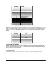
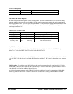
When reading the data record, the program should read each data byte at N+2 while monitoring the status byte at address
N+3. The status byte consists of 3 bits of information. Bit 0 is the ‘busy’ bit, Bit 1 is the ‘freeze’ bit and Bit 2 is the ‘not
empty’ bit. Bits 3-7 of the status byte are not used. The following is an explanation of the Secondary FIFO registers and
the three status bits: