


170 • Chapter 7 Application Programming DMC-1700/1800
AI1 Wait for input 1
PR 6370 Distance
SP 3185 Speed
BGX Start Motion
AMX After motion is complete
SB1 Set output bit 1
WT 20 Wait 20 ms
CB1 Clear output bit 1
WT 80 Wait 80 ms
JP #A Repeat the process
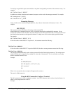
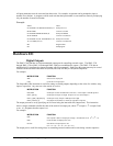
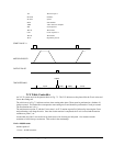
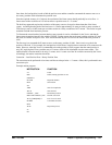
START PULSE I1
MOTOR VELOCITY
OUTPUT PULSE
TIME INTERVALS
move
output
wait ready move
Figure 7.1 - Motor Velocity and the Associated Input/Output signals
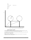
X-Y Table Controller
An X-Y-Z system must cut the pattern shown in Fig. 7.2. The X-Y table moves the plate while the Z-axis raises and
lowers the cutting tool.
The solid curves in Fig. 7.2 indicate sections where cutting takes place. Those must be performed at a feedrate of 1
inch per second. The dashed line corresponds to non-cutting moves and should be performed at 5 inch per second.
The acceleration rate is 0.1 g.
The motion starts at point A, with the Z-axis raised. An X-Y motion to point B is followed by lowering the Z-axis
and performing a cut along the circle. Once the circular motion is completed, the Z-axis is raised and the motion
continues to point C, etc.
Assume that all of the 3 axes are driven by lead screws with 10 turns-per-inch pitch. Also assume encoder
resolution of 1000 lines per revolution. This results in the relationship:
1 inch = 40,000 counts
and the speeds of
1 in/sec = 40,000 count/sec