


112 • Chapter 6 Programming Motion DMC-1700/1800
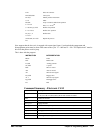
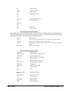
Operand Summary - Electronic CAM
command description
_EB Contains State of ECAM
_EC Contains current ECAM index
_EGx Contains ECAM status for each axis
_EM Contains size of cycle for each axis
_EP Contains value of the ECAM table interval
_EQx Contains ECAM status for each axis
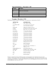
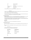
Example - Electronic CAM
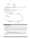
The following example illustrates a cam program with a master axis, Z, and two slaves, X and Y.
INSTRUCTION INTERPRETATION
#A;V1=0 Label; Initialize variable
PA 0,0;BGXY;AMXY Go to position 0,0 on X and Y axes
EA Z Z axis as the Master for ECAM
EM 0,0,4000 Change for Z is 4000, zero for X, Y
EP400,0 ECAM interval is 400 counts with zero start
ET[0]=0,0 When master is at 0 position; 1
st
point.
ET[1]=40,20 2
nd
point in the ECAM table
ET[2]=120,60 3
rd
point in the ECAM table
ET[3]=240,120 4
th
point in the ECAM table
ET[4]=280,140 5
th
point in the ECAM table
ET[5]=280,140 6
th
point in the ECAM table
ET[6]=280,140 7
th
point in the ECAM table
ET[7]=240,120 8
th
point in the ECAM table
ET[8]=120,60 9
th
point in the ECAM table
ET[9]=40,20 10
th
point in the ECAM table
ET[10]=0,0 Starting point for next cycle
EB 1 Enable ECAM mode
JGZ=4000 Set Z to jog at 4000
EG 0,0 Engage both X and Y when Master = 0
BGZ Begin jog on Z axis
#LOOP;JP#LOOP,V1=0 Loop until the variable is set
EQ2000,2000 Disengage X and Y when Master = 2000
MF,, 2000 Wait until the Master goes to 2000
ST Z Stop the Z axis motion
EB 0 Exit the ECAM mode
EN End of the program
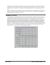
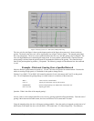
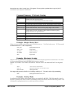
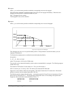
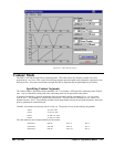
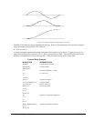
The above example shows how the ECAM program is structured and how the commands can be given to the
controller. The next page provides the results captured by the WSDK program. This shows how the motion will be
seen during the ECAM cycles. The first graph is for the X axis, the second graph shows the cycle on the Y axis and
the third graph shows the cycle of the Z axis.