


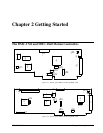

10 • Chapter 2 Getting Started DMC-1700/1800
For servo motors in current mode, the amplifiers should accept an analog signal in the +/-10 Volt range
as a command. The amplifier gain should be set such that a +10V command will generate the
maximum required current. For example, if the motor peak current is 10A, the amplifier gain should
be 1 A/V. For velocity mode amplifiers, a command signal of 10 Volts should run the motor at the
maximum required speed. Set the velocity gain so that an input signal of 10V, runs the motor at the
maximum required speed.
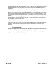
For step motors, the amplifiers should accept step and direction signals. For start-up of a step motor
system refer to Step 8c “Connecting Step Motors”.
The WSDK software is highly recommended for first time users of the DMC-1700/1800. It provides step-by-step
instructions for system connection, tuning and analysis.
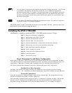
Installing the DMC-1700/1800
Installation of a complete, operational DMC-1700/1800 system consists of 9 steps.
Step 1. Determine overall motor configuration.
Step 2. Install Jumpers on the DMC-1700/1800.
Step 3. Install the communications software.
Step 4. Install the DMC-1700/1800 in the PC.
Step 5. Establish communications with the Galil Communication Software.
Step 6. Determine the Axes to be used for sinusoidal commutation.
Step 7. Make connections to amplifier and encoder.
Step 8a. Connect standard servo motors.
Step 8b. Connect sinusoidal commutation motors
Step 8c. Connect step motors.
Step 9. Tune the servo system
Step 1. Determine Overall Motor Configuration
Before setting up the motion control system, the user must determine the desired motor configuration. The DMC-
1700/1800 can control any combination of standard servo motors, sinusoidally commutated brushless motors, and
stepper motors. Other types of actuators, such as hydraulics can also be controlled, please consult Galil.
The following configuration information is necessary to determine the proper motor configuration:
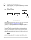
Standard Servo Motor Operation:
The DMC-1700/1800 has been setup by the factory for standard servo motor operation providing an analog
command signal of +/- 10V. No hardware or software configuration is required for standard servo motor operation.
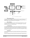
Sinusoidal Commutation:
Sinusoidal commutation is configured through a single software command, BA. This configuration causes the
controller to reconfigure the number of available control axes.
Each sinusoidally commutated motor requires two DAC’s. In standard servo operation, the DMC-1700/1800 has
one DAC per axis. In order to have the additional DAC for sinusoidal commutation, the controller must be
designated as having one additional axis for each sinusoidal commutation axis. For example, to control two