


DMC-1700/1800 Appendices • 221
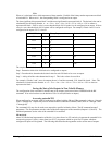
Argument Blocks Bits Description
m 0 1-8 General Outputs
a 2,3 17-32 Extended I/O
b 4,5 33-48 Extended I/O
c 6,7 49-64 Extended I/O
d 8,9 65-80 Extended I/O
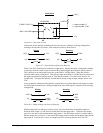
For example, if block 8 is configured as an output, the following command may be issued:
OP 7,,,,7
This command will set bits 1,2,3 (block 0) and bits 65,66,67 (block 8) to 1. Bits 4 through 8 and bits 68 through 80
will be set to 0. All other bits are unaffected.
When accessing I/O blocks configured as inputs, use the TIn command. The argument ‘n’ refers to the block to be
read (n=0,2,3,4,5,6,7,8 or 9). The value returned will be a decimal representation of the corresponding bits.
Individual bits can be queried using the @IN[n] function (where n=1 through 8 or 17 through 80). If the following
command is issued;
MG @IN[17]
the controller will return the state of the least significant bit of block 2 (assuming block 2 is configured as an input).
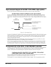
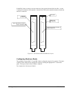
Configuring the 64 Extended I/O of the DMC-1750 to 1780 and 1850
to 1880 using the DB-14064
The 5 to 8 axis versions of the DMC-1700/1800 are equipped with 24 inputs and 16 outputs (an increase from 8
inputs and 8 outputs on 1 to 4 axis models). Since the numbering system for accessing the extended I/O ranges from
17 to 80, there will be an overlap of inputs from 17 to 24. When configuring the I/O, note that the first bank of
extended I/O (17-24) will only be accessible as outputs. Configuring the first block (17-24) as inputs renders them as
“no connection” inputs, since these inputs are already accessible through the general I/O on the main board.
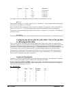
The procedure for configuring and accessing the extended I/O on the 5-8 axis versions is then similarly done as
described in the previous section. Except, when using the OP command, the argument “m” is a decimal number
from 0 to 65535, which refers to the first 16 general I/O.
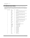
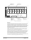
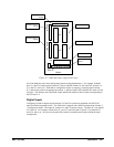
Connector Description:
The DMC-17x8 controller (and DB-14064) has two 50 Pin IDC header connectors. The connectors are compatible
with I/O mounting racks such as Grayhill 70GRCM32-HL and OPTO-22 G4PB24.
Note for interfacing to OPTO-22 G4PB24: When using the OPTO-22 G4PB24 I/O mounting rack, the user will
only have access to 48 of the 64 I/O points available on the controller. Block 5 and Block 9 must be configured as
inputs and will be grounded by the I/O rack.
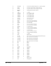
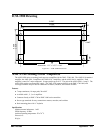
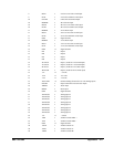
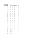
J6 50-PIN IDC
Pin Signal Block
Bit @IN[n],
@OUT[n]
Bit
No
1. I/O 4 40 7
3. I/O 4 39 6
5 I/O 4 38 5
7. I/O 4 37 4
9. I/O 4 36 3
11. I/O 4 35 2
13. I/O 4 34 1