


EQUIPMENT CHECK-OUT AND ADJUSTMENTS
6-2
February 1996
Part No. 004-3039-274
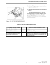
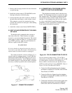
7. Observe the LEDs on the channel modules. On
module-based consoles, each channel module
should have either the yellow or green LED adja-
cent to the volume control on.
Touch the volume control cap on individual chan-
nel modules. The LEDs should toggle smoothly
between yellow and green, with no delay as the cap is
touched.
In normal operation, auxiliary switch and paging
modules may show no indications until the function is
actually used. Think before you press buttons! You
could interfere with other operations or accidentally
set off pagers and sirens.
8. If at this point, the CPP and all console positions
appear to be performing normally, proceed ahead to
level setting and point by point testing.
NOTE: The system should be allowed to "burn-in"
for a minimum of 72 hours, before being placed into
actual service, to allow any possible "infant mor-
tality" problems to surface and be resolved.
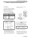
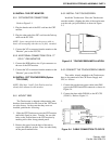
6.2 CPP ADJUSTMENTS
The only level to be adjusted in the CPP is the Tx
Output from each Line Interface Controller. Rx lev-
els are automatically adjusted under processor con-
trol. The initial Tx and Rx level settings are factory
adjusted and programmed in accordance with the data
furnished to E.F. Johnson at the time of order. Tx lev-
els should be set using industry standard techniques
for 600W balanced line audio.
NOTES:
The receive input for each channel will be pro-
grammed for either 2 wire or 4 wire audio input in
accordance with the data furnished at the time of
order. The 2 wire receive audio path is disabled on
any channel specified by the customer as having a 4
wire interface.
All DC controlled channels are shipped with the DC
current generator appliqu board disconnected to pre-
vent accidental electric shock injury to the installer.
These appliqu s must be plugged in prior to testing
any DC controlled channels.
The Tx and Rx levels between the CPP and the
Console are fixed and cannot be adjusted. The nomi-
nal level is 0 dBm across 600W. If the console is
being operated through a Remote Interface Adapter
(RIA), level adjustment is automatically maintained
through ALC amplifiers.
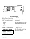
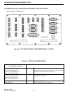
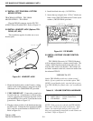
6.3 CONSOLE ADJUSTMENTS
There are several control adjustments that can be
made to optimize the performance of the console.
These adjustments are located on the right side of the
control tray when viewed from the front of the con-
sole.
Panel Microphone
The sensitivity of the panel (or primary) micro-
phone is adjusted by the MIC 1 control, R11. This
control should be adjusted to just below the knee of
compression for a typical operator speaking in a nor-
mal voice at the normal working distance from the
microphone. If set too high, the mobile units will
complain about excessive background noise and a
"barrel" quality to the dispatcher’s voice. This is
caused by excessive compressor action on the control
tray.
NOTE: The MIC 1 and MIC 2 controls are SENSITIV-
ITY adjustments, not OUTPUT adjustments. The
audio level from the tray is fixed and cannot be
increased through the use of these controls.
Auxiliary Microphone
If the console is equipped with an Auxiliary (or
secondary) microphone, such as a desk microphone at
an NCIC terminal, it’s sensitivity can be adjusted by
the MIC 2 control, R16. See the paragraph above for
details.
Headset Transmit
The transmit sensitivity of the headset lipmicro-
phone is adjusted by the HS control, R6. Note that
many amplified headsets have an internal compressor
as part of the headset mic circuitry. Be sure the con-
sole HS control is set just below the knee of compres-
sion to avoid double or constant compression.