


3-1
February 1996
Part No. 004-3039-274
CABINETRY ASSEMBLY FOR CRT CONSOLE SYSTEMS
SECTION 3 CABINETRY ASSEMBLY FOR CRT CONSOLE SYSTEMS
3.1 INTRODUCTION
This section contains the instructions to assem-
ble VR-CM50 CABINETRY. If you purchased a
complete VR-CM50 system, most electronic compo-
nents will be pre-installed in your VR-CM50 cabine-
try.
3.2 TOOLS REQUIRED
The following tools are needed for mechanical
assembly of the TDM-150 Console cabinetry.
#2 Phillips Screwdriver
Power Screwdriver with #2 Phillips Bit
3/8" Open End Wrench
7/16" Open End Wrench
1/2" Open End Wrench
3/8" Square Drive 7/16" Socket
Carpenter’s Level
White Carpenter s Glue (Required only if multiple
writing surfaces must be joined)
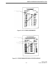
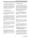
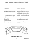
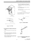
3.3 CONSOLE ARRANGEMENT
Consoles are shipped in 2, 3 or 4 bay sections
depending on the final cabinet configuration. Before
assembly begins, arrange the console sections (bays)
in their proper room layout positions. Individual sec-
tions will be identified with letters A , B , and C ,
beginning with left-most section. The letter designa-
tions will appear on the inside ends of the console
frame. Refer to your proposal diagram for the correct
layout positions. A sample proposal diagram is shown
in Figure 3-1.
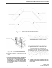
It is important to note that the console sections
should not be forced to conform to surrounding walls
or structures. This will ultimately bend the console
frames so that the Formica will not fit properly as
designed.
Once the Formica writing surface is permanently
mounted, DO NOT ATTEMPT TO MOVE THE
CONSOLES!
Figure 3-1 SAMPLE CONSOLE LAYOUT