


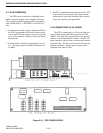

CENTRAL PROCESSOR PACKAGE INSTALLATION
2-12
February 1996
Part No. 004-3039-274
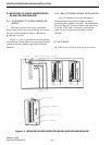
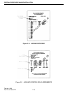
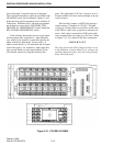
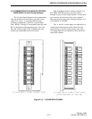
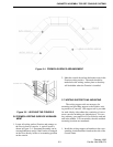
2.10 DISPATCH POSITION CONNECTIONS
Each dispatch position will plug directly into the
J1 connector on the PIC line terminator board as
shown in Figure 2-15. Console positions having more
than four speakers will have two or more PICs and
line terminator boards assigned. A label on the top of
the line terminator board, as shown in Figure 2-15,
will identify the position with the Console ID. The
jumpers on the line terminator board determine
whether the selected audio is sent to the left or right
speaker on the console. Refer to the VR-CM50 Con-
sole Service Manual to adjust them. Refer to Section
2.6 for grounding information.
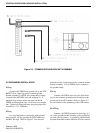
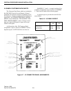
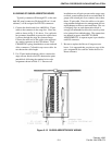
2.11 VOTER SYSTEM CONNECTIONS
If this system is specified for use with a voter
system, the CPP is equipped with a TDM-AUX/V
card for each voter shelf to be connected. The connec-
tion to each voter is through a 25 pair, male ribbon
connector and a local interface board to be installed at
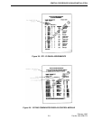
the voter shelf. The I/O CONNECTOR PANEL
ASSIGNMENTS report will define the connector
position for each voter. The VOTING COMPARA-
TOR DISPLAY/CONTROL MODULE report, as
shown in Figure 2-9, defines the site and control con-
nections. This report is formatted for either General
Electric or Motorola voters in accordance with the
data furnished to E.F. Johnson at the time of order.
These reports are interleaved with the RTL I/O PAIR
ASSIGNMENTS sheets at the designated connector
locations. Refer to the VR-CM50 Voter Modification
Kit Installation Guide - P/N 700901 ECL A, for spe-
cific voter shelf connection details.
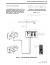
2.12 LOGGING RECORDER CONNECTIONS
Mixed Tx/Rx audio for each individual channel
is provided for connection to a logging recorder. The
logging recorder output is a 600W balanced line at a
level of -10 dBm. On tone controlled channels, the
transmit audio will be stripped of guard tone (2175
hz) and function tones. On DC controlled channels,
the transmit audio is DC blocked.
In the case of multi-receiver base stations, the
audio from all receivers is summed with the transmit
audio by bridging the logging recorder outputs of the
LIC and the QRC cards. Jumpers on the QRC card,
associated with the base station, can be set to isolate
individual receiver audio, if required.
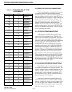
Table 2-3 STANDARD COLOR CODE
ASSIGNMENTS
CABLE LINE COLOR
Pair
1
1
2
White/Blue
Blue/White
Pair
2
3
4
White/Orange
Orange/White
Pair
3
5
6
Green/White
White/Green
Pair
4
7
8
White/Brown
Brown/White
Pair
5
9
10
White/Slate
Slate/White
Pair
6
11
12
Red/Blue
Blue/Red
Pair
7
13
14
Red/Orange
Orange/Red
Pair
8
15
16
Red/Green
Green/Red
Pair
9
17
18
Red/Brown
Brown/Red
Pair
10
19
20
Red/Slate
Slate/Red
Pair
11
21
22
Black/Blue
Blue/Black
Pair
12
23
24
Black/Orange
Orange/Black
Pair
13
25
26
Black/Green
Green/Black
Pair
14
27
28
Black/Brown
Brown/Black
Pair
15
29
30
Black/Slate
Slate/Black
Pair
16
31
32
Yellow/Blue
Blue/Yellow
Pair
17
33
34
Yellow/Orange
Orange/Yellow
Pair
18
35
36
Yellow/Green
Green/Yellow
Pair
19
37
38
Yellow/Brown
Brown/Yellow
Pair
20
39
40
Yellow/Slate
Slate/Yellow
Pair
21
41
42
Violet/Blue
Blue/Violet
Pair
22
43
44
Violet/Orange
Orange/Violet
Pair
23
45
46
Violet/Green
Green/Violet
Pair
24
47
48
Violet/Brown
Brown/Violet
Pair
25
49
50
Violet/Slate
Slate/Violet