CRT-BASED ELECTRONICS ASSEMBLY PART II
5-3
February 1996
Part No. 004-3039-274
5.5 INSTALL THE CRT MONITOR
5.5.1 CRT MONITOR CONNECTIONS
Refer to Figure 5-1.
1. Plug the female end of the IEC cord into the CRT
monitor.
2. Plug the other end of the IEC cord into the 2nd top
outlet on the PC UPS.
NOTE: Leave enough slack on the power cable so
that it will not unplug when the tray is fully extended.
3. Connect the VGA connector from the monitor to the
"Monitor" port on the PC CPU.
5.5.2 ADDITIONAL CONNECTION FOR A 17 "
OR 21 " IDEK MONITOR
1. Connect the RGB cable to the 15 pin connector on
the rear of the CRT monitor.
2. Connect the VGA connector from the monitor to the
"Monitor" port on the PC CPU.
5.6 INSTALL CRT TOUCHSCREEN (Option
TDV-OP492)
NOTE: Skip Steps 1 and 2 if the Touchscreen has
already been mounted on the monitor.
5.6.1 MOUNT TABS
The Touchscreen is shipped with mounting tabs
that have been installed on the front of the CRT moni-
tor at the factory. In the event that they were not
installed, perform the following:
1. Slide the CRT Touchscreen onto the CRT monitor
and hold it firmly in place. Transfer the two side
holes on the Touchscreen to the CRT monitor by
marking with a thin sharp-pointed pencil.
2. Remove the paper from the back of the tabs to
expose the adhesive surface. Place the tabs firmly
on the pencil-marked holes.
5.6.2 INSTALL THE TOUCHSCREEN
Install the Touchscreen: Place the Touchscreen
onto the monitor, slipping the sides of the touchscreen
over the tabs you just installed, as shown in Figure
5-3.
Figure 5-3 TOUCHSCREEN INSTALLATION
5.6.3 CONNECT THE TOUCHSCREEN CABLES
Two cables, already attached to the Touchscreen,
have to be connected to the CIP Power Supply and
CPU as follows:
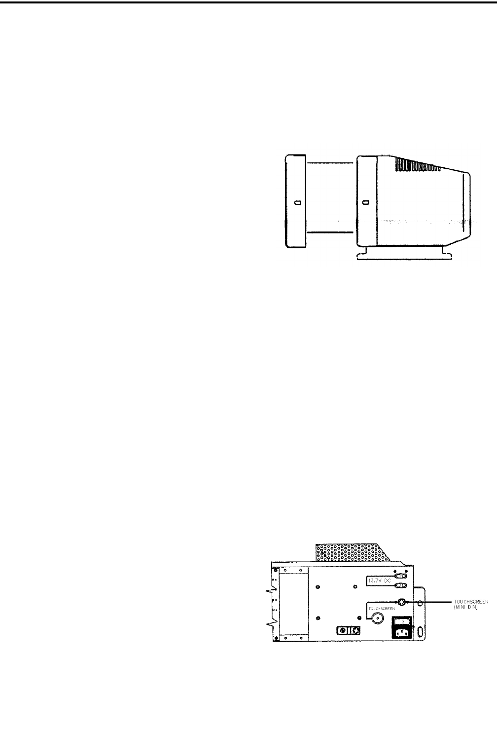
1. Connect the touchscreen power cable (mini DIN
type) to the CIP PS mini DIN connector as shown in
Figure 5-4.
2. Connect the data cable (DE9-M) to the PC CPU
(COM 1). Refer to Figure 5-1.
3.
Figure 5-4 CABLE CONNECTION TO CIP PS


