


CENTRAL PROCESSOR PACKAGE INSTALLATION
2-13
February 1996
Part No. 004-3039-274
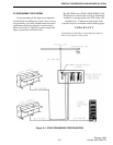
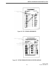
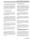
Typically, logging recorder audio appears on con-
nector P14 on the standard I/O panel (connector P7 on
14 card CPP cabinets). If the CPP is housed in more
than one cabinet, a separate logging recorder output
will be provided from each cabinet to minimize the
need for intercabinet wiring. Logging recorder con-
nections are defined in reports titled RTL I/O PAIR
ASSIGNMENTS , as shown in Figure 2-10. A sepa-
rate report is provided for each connector.
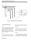
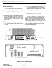
2.13 PRINTER INSTALLATION
The Logging Diagnostic Printer option, TDM-
OP205 is strongly recommended. In the event of a
system reset, either manually or automatically initi-
ated, the printed record is the only way to determine
what actually happened.
Assemble the printer stand in accordance with the
instructions supplied. If your CPP is housed in a 60"
cabinet, the printer may be placed on top of the CPP.
If your CPP is housed in an 88" cabinet, a separate
printer shelf will be required. Do not attempt to mount
the printer in the CPP cabinet. Unpack the printer and
remove all shipping material. Insert the paper, making
sure the tractor feed in engaged and the friction feed is
disengaged.
Two 120 VAC convenience outlets for the printer
and modem transformer are located in the upper left
side of the CPP vent housing. If your CPP is housed
in a 26" cabinet, the printer can be placed on top of the
CPP, but no outlet is provided.
Special note for 230 volt system users: The printer
supplied with your system is configured for 120 VAC
operation. The convenience outlets on the CPP are
powered via an approved 230V/120V step-down
transformer. The printer must be connected to this
outlet.
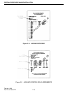
Connect the printer to the port on the I/O panel
designated in the I/O CONNECTOR PANEL
ASSIGNMENTS report. Usually, this is P15 on 60"
and 88" cabinets, P8 on 26" cabinets. The printer has
been programmed and tested prior to shipment. Refer
to the printer instruction manual should problems be
encountered.
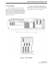
2.14 MODEM INSTALLATION
This system is equipped with a modem to allow
remote diagnostics and programming via a dial-up
phone line. The modem has been properly configured
for 2400 baud operation and tested at the factory prior
to shipment. Do not change the modem programming
without specific authorization from E.F. JOHNSON
Technical Support. If you wish to access the system
via modem, your PC must be equipped with TDM-
OP208/PC Maintenance Software. Contact E.F.
Johnson Technical Support for details.
Connect the RS232 jack on the modem to the
modem port on the I/O panel designated in the I/O
CONNECTOR PANEL ASSIGNMENTS report.
Usually, this is P17 on 60" and 88" cabinets, P10 on
26" cabinets.
Two 120 VAC convenience outlets for the modem
transformer and printer are located in the upper left
side of the CPP vent housing on 60" and 88" cabinets.
If your CPP is housed in a 26" cabinet, no outlet is
provided.
Special note for 230 volt system users: The modem
transformer supplied with your system is designed for
120 VAC operation. The convenience outlets on the
CPP are powered via an approved 230V/120V step-
down transformer. The modem must be connected to
one of these outlets.
Connect the RJ-11 modular LINE jack on the
modem to the telephone line designated for modem
communications. If additional instruments are to be
routed through the modem for voice use, these should
be connected to the RJ-11 PHONE jack on the
modem.
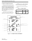
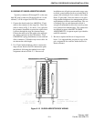
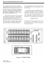
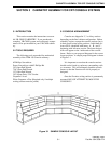
2.15 CONNECTION TO AUXILIARY CONTROL
FUNCTIONS (Standard Cabinet)
If the console was ordered with auxiliary switch
functions specified, the CPP cabinet will have one or
more auxiliary relay panels installed. A typical relay
panel is shown in Figure 2-13. The standard relay
panel, furnished with a TDM-AUX includes eight
relays. An additional eight relays can be added by
specifying option TDM-AUX/E8. Relays 1 through 8
are located at the bottom of the panel. Expansion