


CRT-BASED ELECTRONICS ASSEMBLY PART II
5-5
February 1996
Part No. 004-3039-274
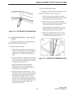
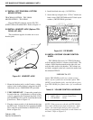
1. Remove the hole plug from the left side of the head-
set jack housing.
2. Install the volume control (4751904Z5001) in the
housing in the place of the hole plug.
3. Connect the three pin molex connector, located on
the end of the wire harness, to the volume control.
This connector can only be connected one way.
Caution: Be careful not to bend pins when making
the connection.
4. Attach the volume control knob (240FPV12BA1).
5.10 SET UP AND OPERATION OF THE HEAD-
SET JACK
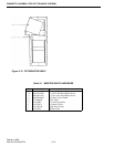
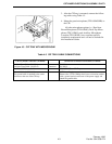
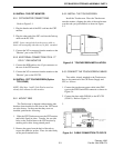
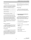
The headset jack is equipped with a switch on
both sides of the unit. These switches are slightly
recessed to prevent accidental movement. The switch
on the right, as shown in Figure 5-7, is used for select-
ing 4W/6W operation. Four wire (4W) headsets do
not have a push-to-talk (PTT) switch.
W A R N I N G
If a 4 wire headset is plugged into the jack when it is
set for 6 wire operation, the channel will instantly key
up and remain on until the headset is unplugged.
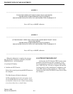
The switch on the left, as shown in Figure 5-7, is
typically used for training purposes. In the MIC On
position, the headset MIC and earpiece are active for
normal dispatch operation. In the MIC Off position,
the headset earpiece is active but the MIC is disabled
for use by a trainee in parallel with a trained operator.
Figure 5-7 CONNECTOR HEADSET
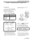
5.11 CONNECTING A TELEPHONE INSTRU-
MENT TO THE TELCO INTERFACE
The telephone instrument must be headset com-
patible. The instrument must have a separate mic path
and earpiece path. The telephone instrument should
also provide a contact closure output when a line is
selected. If the telephone does not have this capabil-
ity, a key on the Radio Control Panel may be pro-
grammed to switch from Radio to Telephone but this
is not a preferred method of operation.
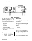
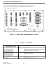
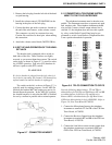
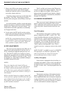
Figure 5-8 TELCO CONNECTION TO CIP PS
Note the following abbreviations: TT and TR are
abbreviations for Talk Tip and Talk Return. RT and RR
are abbreviations for Receiver Tip and Receiver
Return. OHS is an abbreviation for Off-Hook Sense.
GND is an abbreviation for logic GROUND. Refer to
Figure 5-8, Line Term Board A1709230.
1. Connect the Microphone Input to the telephone
instrument to terminals TT and TR of the CIP Line
Term Board, A1709230.
2. Connect the Receiver Output from the telephone
instrument to terminals RT and RR of the CIP Line
Term Board, A1709230.
3. Connect the Line Select contact closure output from
the telephone instrument to terminals OHS and
GND of the CIP Line Term Board, A1709230.