


CENTRAL PROCESSOR PACKAGE INSTALLATION
2-11
February 1996
Part No. 004-3039-274
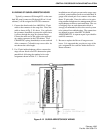
2.9 WIRING OF SURGE ARRESTOR BOXES
Typically, connectors P9 through P13 on the stan-
dard I/O panel (connectors P4 through P6 on 14 card
cabinets) will be assigned for RTL I/O connectors.
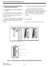
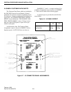
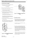
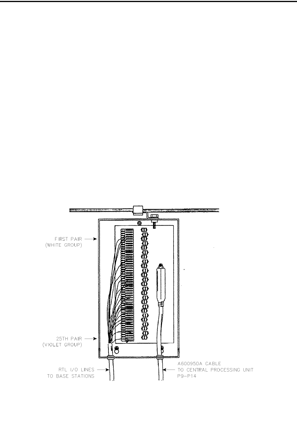
1. Connect the female end of an A600950A, 25 pair
cable to the connector in the surge box. Dress the
cable as shown in Fig. 2-10. above. Use a split rub-
ber grommet (furnished) to protect the cable where
it passes through the surge box bottom flange.
Connect the male end of this cable to the appropri-
ate mating connector in the CPP cabinet. Use a
CHAMP LOC spring (furnished) to secure each end
of the connector. Coil and tie any excess cable - do
not shorten the cable length.
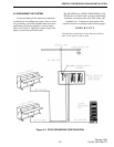
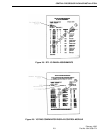
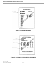
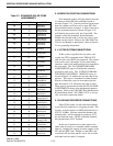
2. Use 25 pair inside telephone cable to connect the
surge arrestor block to an RTL demarcation point
punch block following the standard color code
assignment shown in Table 2-3. Since not all
installations use all pairs present on the surge arres-
tor block, some installers prefer to use individual 24
gauge solid twisted pair cross-connect wires rather
than a 25 pair cable. Dress the cable or wire pairs
using standard telephone wire management devices
and techniques to effect a neat installation. The use
of bridging clips on each demarcation block is
strongly recommended to allow the console system
to be isolated for troubleshooting. The connections
are defined in reports titled RTL I/O PAIR
ASSIGNMENTS. A separate report is provided for
each I/O connector.
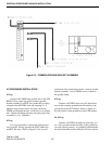
3. Be sure to replace the lids on all surge arrestor
boxes. It is suggested that you place a copy of the
pair assignments for each box inside the box for
future reference.
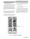
Figure 2-12 SURGE ARRESTOR BOX WIRING