


2-1
February 1996
Part No. 004-3039-274
CENTRAL PROCESSOR PACKAGE INSTALLATION
SECTION 2 CENTRAL PROCESSOR PACKAGE INSTALLATION
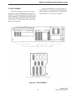
2.1 LOCATION OF THE CENTRAL PROCES-
SOR PACKAGE (CPP)
In selecting a location for the Central Processor
Package (CPP) equipment cabinet, the following crite-
ria should be considered:
1. Avoid locations which are subject to high ambient
temperatures, excessive moisture, flooding, exces-
sive dust or infestation by insects or small animals.
2. The cabinet must be placed in an indoor location
having a floor area large enough to allow access to
both the front and rear of the cabinet. The minimum
cabinet size is 21" wide by 26" deep. In addition,
wall space will be required for the common ground
bracket, surge arrestor box(es) and any additional
RTL punch block(s).
3. A single, 120 VAC, 15/20 amp dedicated branch cir-
cuit is required for CPPs of 60 card capacity or less.
Two such branch circuits are required for packages
equipped with 60 to 120 cards. Systems ordered
with options TDM-OP200/E, /GB, /I and /NZ
require 230 VAC circuits. If the building is
equipped with an emergency generator, the CPP
branch circuits should be part of the emergency
power system.
4. An earth ground bond must be provided. A contin-
uous copper cold water pipe or driven copper
ground rod are suitable grounds. Electrical conduit,
steam lines, sprinkler system lines, utility mains or
building steel may not be used as ground bonds.
Note: Verify the ground integrity yourself. It is
risky to blindly trust grounds used by others.
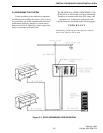
5. The cable run to any console location may not
exceed 4000 feet, using E.F. Johnson-provided
cable. If the console is located in a different build-
ing or if the cable route places its proximity to other
electrical lines that can induce interference, the use
of a Remote Interface Adapter (RIA) is required.
6. In placement of the cabinet, the front door of the
enclosure must be readily accessible for service.
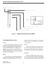
7. A connection to an outside telephone line is required
for diagnostic modem access. If a dedicated
modem line cannot be provided, an administrative
line or a phone patch line can be used by routing the
line through the modem. Programming the modem
to auto-answer after several rings, will allow the
line to be used for normal voice operation as well as
CPP diagnostics.
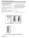
8. Mounting space will be required for the system
diagnostic printer (TDM-OP205). If the CPP is
housed in a 60" cabinet, the printer can be placed on
top of the CPP. If the CPP is housed in a 88" cabi-
net, a shelf must be provided for the printer. The
printer is supplied with a table-top stand which pro-
vides paper supply storage and an output tray. Do
not attempt to mount the printer inside the CPP cab-
inet.
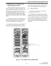
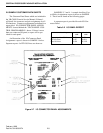
2.2 ASSEMBLY OF THE CENTRAL PROCES-
SOR PACKAGE (CPP) CABINETRY
If the CPP is housed in a single cabinet (30 cards
or less in a 60" cabinet, 60 cards or less in a 88" cabi-
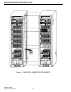
net), no field assembly is required. If the CPP
requires two or more cabinets, each cabinet section
will be shipped separately to facilitate handling.
Assembly of the cabinets is illustrated below in Fig-
ure 2-1. Be sure to install all of the required hard-
ware; do not omit any bolts or lockwashers.
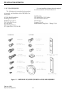
The hardware in Table 2-1 is included in Assem-
bly A2809201 for joining 2 - 60" CPU Cabinets and
Assembly A2809301 for joining 2 - 88" CPU Cabi-
nets:
Table 2-1 CPU CABINET HARDWARE
Qty. Part No. Description
Joining 2 - 60" CPU Cabinets
6
6
2
28011H0B2012
280211082041
240B25312420
1/4"-20 Hex Bolt
1/4"-20 Keps Nut
2.5" Bushing Snap Ring
Joining 2 - 88" CPU Cabinets
8
8
2
28011H0B2012
280211082041
240B25312420
1/4"-20 Hex Bolt
1/4"-20 Keps Nut
2.5" Bushing Snap Ring